

This is a general, instructive guide to how the system works and what to look for. It is not a service manual, and it is not specific to your truck. Procedures, clearances, pressures, torque figures and service limits differ between makes, models and build dates, and the manual for the machine you are actually working on is the only authority on what is correct for it. Work to that manual, and to your employer's safety procedures. The illustrations show one manufacturer's design; there are many, so read them as examples of the arrangement rather than as a picture of your machine.
How a steering axle works
A steering axle is a simple assembly doing two jobs at once. It has to steer the truck, and it has to stay in contact with the ground when the ground is not flat. The first job belongs to a hydraulic cylinder and a pair of tie rods; the second belongs to a single pin through the middle of the axle.
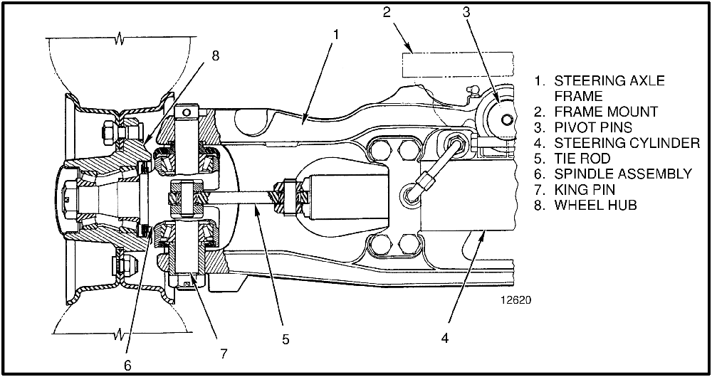
The assembly is an axle frame, a steering cylinder, and two spindle and hub assemblies. The axle is articulated: it hangs from a frame mount on a center pivot pin, and that pin lets the whole axle rotate as the truck travels over rough surfaces, so both wheels stay loaded instead of one lifting clear.
The center pivot
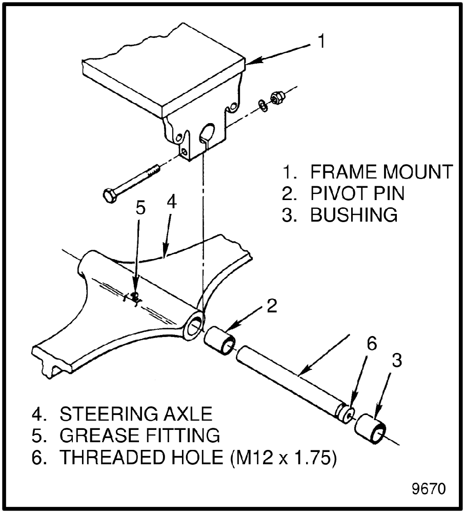
The pivot pin runs in bushings in the frame mount and is held in place by a single bolt. A grease fitting serves it. The pin itself is tapped at one end so a threaded puller can be screwed in to draw it out, which is the only practical way to remove it once it has been in service. On trucks where the counterweight sits behind the mount, there is usually an access hole through the counterweight to reach it.
The steering cylinder
Steering uses one double-acting cylinder mounted across the axle, with the piston rod passing right through so an end emerges from both ends of the shell. A single piston, with its seal, sits in the middle of that rod. Oil pressure on one side of the piston moves it along the bore, and as it moves it pushes an equal amount of oil out of the other side. Because the rod is the same diameter on both sides of the piston, the displaced volume matches and the axle steers at the same rate in both directions.
When the piston reaches the end of its travel and the operator keeps turning, something has to give. A relief valve in the hydraulic pump takes the pressure at that point, which is why the steering relief setting is a pump-side check rather than an axle-side one.
Tie rods connect the spindle arms to the ends of the cylinder rod, and they are not adjustable. There is no toe setting to make on this axle; geometry is fixed by the parts.
The cylinder is bolted to the axle frame, and the mounting is not the same on every axle. Both four-bolt and eight-bolt patterns are used, and the tightening figures are not the same for each. Some axles also carry shims under the bottom cylinder mount. Count the bolts before you order hardware or set a torque wrench, and note the shim arrangement as the cylinder comes off so the same shims go back under the same mount.
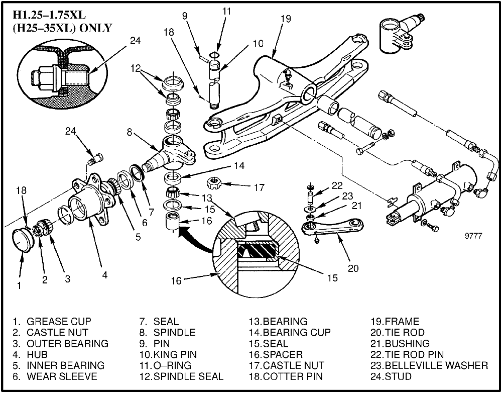
Inside, the cylinder is conventional: rod, shell, an end cap at each end, and a seal stack made up of a wiper ring, a rod seal, back-up rings and O-rings, with a piston seal and a square ring at the piston. The seal arrangement is not the same on every cylinder, and neither is the way the end caps come out. On some the cap is threaded and needs a spanner to unscrew it; on others it pulls straight out of the shell. That is the quickest way to tell which design you are holding, and it decides which seal kit you need. Lay the rings out in the order they come off, because that order is what makes the seal work.
Spindles and king pins
Each spindle swings on a king pin that passes vertically through the axle frame. The spindle turns on two tapered roller bearings, and the king pin is what holds spindle and bearings into the frame. Preload on those bearings is set by a castle nut on the bottom of the king pin, locked with a cotter pin. An O-ring seals the top of the king pin and seals close off the bearings at both ends.
Wheel hubs
Each hub rotates on its own pair of tapered roller bearings and is held on the spindle by a castle nut, which is also what sets the hub bearing preload. A grease cap closes the end. Grease seals keep dirt and water out of the bearings, and a wear sleeve on the spindle protects it from being grooved by the seal lip — the sleeve is sacrificial, and it is cheaper than the part it protects.
What wears out and what fails
- Pivot pin bushings. Checked whenever the axle is off, and replaced if worn or damaged. They carry the whole rear of the truck through one pin.
- Cylinder seals. Rod seals, piston seal, wiper rings, O-rings, back-up rings and the square ring. A leaking cylinder seal shows up as slow or heavy steering rather than as a puddle, because the leak is internal.
- King pin bearings and seals. Two tapered rollers per spindle, with seals top and bottom.
- Hub bearings and seals. Inspected for damage or wear every time a hub comes off.
- Wear sleeves. The part that is meant to wear, so that the hub does not.
- Tie rod pins and bushings, with their Belleville washers.
- The spacer at the king pin. Dirt and corrosion can seize it in the axle frame; there is a machined relief in its top so a bearing puller can get a grip.
- Cotter pins. Never reused — both castle nuts depend on them.
Working safely under a lift truck
Removing the upright, the drive axle, the engine and transmission, or the counterweight causes large changes in the truck's center of gravity. Before removing the upright and drive axle, put blocks under the counterweight so the truck cannot fall backward. Before removing the counterweight, put blocks under the upright assembly so the truck cannot fall forward.
- Block the truck only on a surface that is solid, even and level.
- Every block used to support the truck must be a solid, one-piece unit.
- Confirm the truck is in a stable position before starting work.
- Confirm the lifting device can actually lift the part — a steering axle without its wheels is on the order of 95 kg (210 lb), and the truck's weight on the steering axle is measured in thousands.
- Some trucks have lifting eyes, and those are the points to use for raising the truck to get blocks under it.
The wheels, hubs, bearings, spindles, cylinder and tie rods can all be removed with the axle still in the truck. Dropping the axle means removing the counterweight, so establish first whether the job actually requires it.
Checks and adjustments
Removing air from the steering system
Air gets in whenever a hydraulic line is opened, and it does not need bleed screws to get out again. Check the hydraulic tank is full, start the engine, and rotate the steering wheel from stop to stop several times in each direction. That is enough to clear it. If the steering still feels rough afterwards, the air is not left over from the repair — it is being drawn in, and a loose fitting is the thing to look for.
Checking the steering relief pressure
On most trucks the steering relief valve lives in the hydraulic pump. On some powershift machines there are two: a primary relief in the supply line to the steering control unit, with the pump's own valve acting as a secondary. Establish which arrangement you have before chasing a pressure fault, because adjusting the wrong one achieves nothing.
The check itself is the same in each case. Bring the hydraulic oil up to operating temperature, connect a gauge to the test port at the pump, run the engine at the specified test speed, and hold the steering against the stop so the relief is the only path for the oil. Read the pressure and compare it with the figure for your truck.
Where the valve is adjustable, the acorn nut comes off, the jam nut is loosened, and an adjustment screw raises or lowers the setting; on an in-line primary relief, the valve comes out of the line and a small screwdriver turns the screw clockwise to increase pressure. Recheck after any adjustment. Some pumps have their relief set by the pump manufacturer and are not intended to be adjusted at all.
Relief pressures, test speeds and oil temperatures are specified per truck and differ widely between models and transmission types. Use the figures in your own service data, not a number from another machine.
Setting hub bearing preload
Tapered roller bearings are set by feel and sequence rather than by a single torque figure, and the sequence is what matters:
- Grease both hub bearings, fit the seal and inner bearing to the hub, and put the hub on the spindle.
- Fit the outer bearing, washer and nut, then tighten the nut to the specified seating figure while rotating the hub. Turning it as you tighten is what pulls the rollers square in their cups.
- Back the nut off until the hub turns freely.
- Retighten to the much lower running figure, and lock the nut with a new cotter pin at the first alignment slot that comes up at about that torque.
Setting king pin bearing preload
The same pattern applies at the king pin: fit new bearings and seals, grease them as they go in, make sure a new O-ring goes on at the top of the pin and that the lower seals face the right way, then tighten the castle nut to the seating figure, slacken it back to the low running figure, and lock it with a new cotter pin at the first slot that lines up.
Connect the lines, remove the air from the system by turning the steering wheel from stop to stop with the engine running, and tighten the wheel nuts to the figure for your truck before the machine goes back to work.
Troubleshooting
| Symptom | Possible cause | Procedure or action |
|---|---|---|
| The steered wheels do not move when the steering wheel is turned | The oil level is low, or there is no oil in the tank | Fill the tank. Check for leaks. |
| The steering control unit is damaged | Repair or install a new control unit. | |
| No oil flow from the steering control unit to the steering cylinder | Repair or install new components. Check for leaks. | |
| Slow or difficult steering | Relief valve for the steering system needs adjustment | Adjust the relief valve, or install a new one. |
| Low oil pressure from the hydraulic pump | Check for restrictions, and work through the hydraulic system troubleshooting. | |
| A seal in the steering cylinder has a leak | Install a new seal. | |
| The steering control unit is worn or has damage | Repair or install a new control unit. | |
| The steering wheel turns the tires in the wrong direction | The hydraulic lines are not connected correctly at the steering cylinder, or at the steering control unit | Connect the lines correctly. Remove the air from the system. |
| Steering continues after the steering wheel stops | The steering control unit was assembled wrongly, or has damage | Repair or install a new control unit. |
| There is air in the steering system | The oil level in the tank is low | Add hydraulic oil as necessary. Check for leaks. |
| Air was not removed after a repair to the hydraulic or steering system | Remove the air from the system. | |
| The hydraulic pump has an air leak at the inlet | Repair the system, then remove the air. |
Frequently asked questions
Why does the steering axle pivot in the middle?
So the truck stays on four points of contact over uneven ground. The axle hangs from a single center pivot pin at the frame mount and is free to rotate about it, which lets both steered wheels follow the surface instead of one of them lifting and putting the load on three wheels.
Can I adjust the tie rods to set the toe?
No. The tie rods that connect the spindle arms to the cylinder are not adjustable. If the steering geometry is out, the cause is a worn or bent part rather than a setting, and the fix is replacement.
Steering has gone heavy and slow. Where do I start?
With pressure, before anything comes apart. The listed causes are a relief valve needing adjustment, low pump pressure, a leaking seal inside the steering cylinder, or a worn steering control unit. Gauge the pump test port with the oil warm and the steering held at the stop; that one reading separates a pressure problem from a control unit problem.
How do I bleed the steering after opening a line?
You do not need to crack any fittings. Top up the hydraulic tank, run the engine, and turn the steering wheel from stop to stop several times in each direction. If it is still rough after that, air is getting in somewhere rather than being trapped, so look for a loose fitting or an air leak at the pump inlet.
Do I have to drop the axle to service it?
Usually not. The wheels, hubs, bearings, spindles, cylinder and tie rods can all be removed with the axle still in the truck. Removing the axle itself means taking the counterweight off first, so it is worth being sure the job needs it before starting.
What is the wear sleeve for?
It protects the hub from the seal. The grease seal lip runs against the sleeve rather than against the hub itself, so when the running surface eventually grooves, you replace a sleeve instead of a hub.
Why are there shims under the steering cylinder?
On axles that use them, they set the cylinder's position on the frame. There is no adjustment procedure; the arrangement is recorded as the cylinder comes off, and exactly the same shims go back under the same mount.
Before you order
- Establish which cylinder design you have before ordering seals. Check whether the end cap screws in or pushes in, and count the mounting bolts. The seal arrangement differs between designs, and a kit for the wrong one will not fit.
- Cylinder seal kits should include the wiper rings, rod seals, back-up rings, O-rings, piston seal and square ring together, since they all come out in one job.
- Hub bearings are ordered as bearing and cup together, in pairs per hub, with the grease seals and grease cap.
- Wear sleeves are worth fitting whenever the seals are disturbed.
- King pin work takes a set: king pin, two bearings and cups, upper and lower seals, the O-ring for the top of the pin, the spacer, castle nut and cotter pin.
- Tie rod pins, bushings and Belleville washers are separate parts from the tie rods themselves.
- New cotter pins every time. Both preload settings are held by one.
- Pivot pin bushings and the grease fitting, if the axle is coming out anyway.
We stock steering axle components across the common forklift ranges: cylinder seal kits and complete cylinders, king pin sets, hub bearings, seals and wear sleeves, tie rod ends, pins and bushings, and pivot pin bushings. Send us the truck's serial number, the mounting bolt count and whether the cylinder end caps screw in or push in, and we will match the right design before you order.
This article describes how a hydraulically steered, center-pivoted forklift steering axle is built, what wears in it and how it is checked. Relief pressures, torque figures, preload settings and bolt patterns vary between trucks, build dates and transmission types. As above, work to the service data for your own machine, and block the truck properly before any part of you goes underneath it.