

This is a general, instructive guide to how the system works and what to look for. It is not a service manual, and it is not specific to your truck. Procedures, clearances, pressures, torque figures and service limits differ between makes, models and build dates, and the manual for the machine you are actually working on is the only authority on what is correct for it. Work to that manual, and to your employer's safety procedures. The illustrations show one manufacturer's design; there are many, so read them as examples of the arrangement rather than as a picture of your machine.
How a starter and solenoid work
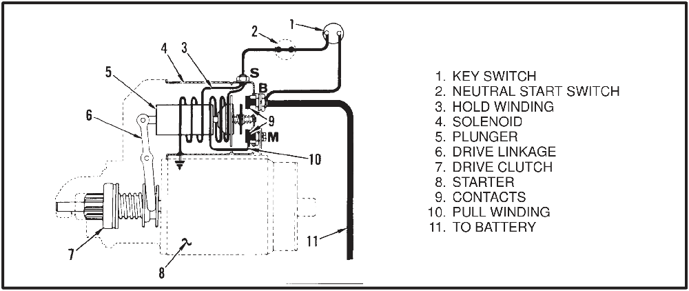
The solenoid does two things in one stroke, in a fixed order. It moves the linkage and the drive clutch to engage the starter pinion with the flywheel ring gear, and only at the end of that stroke does the plunger close the main solenoid contacts so that current reaches the starter windings.
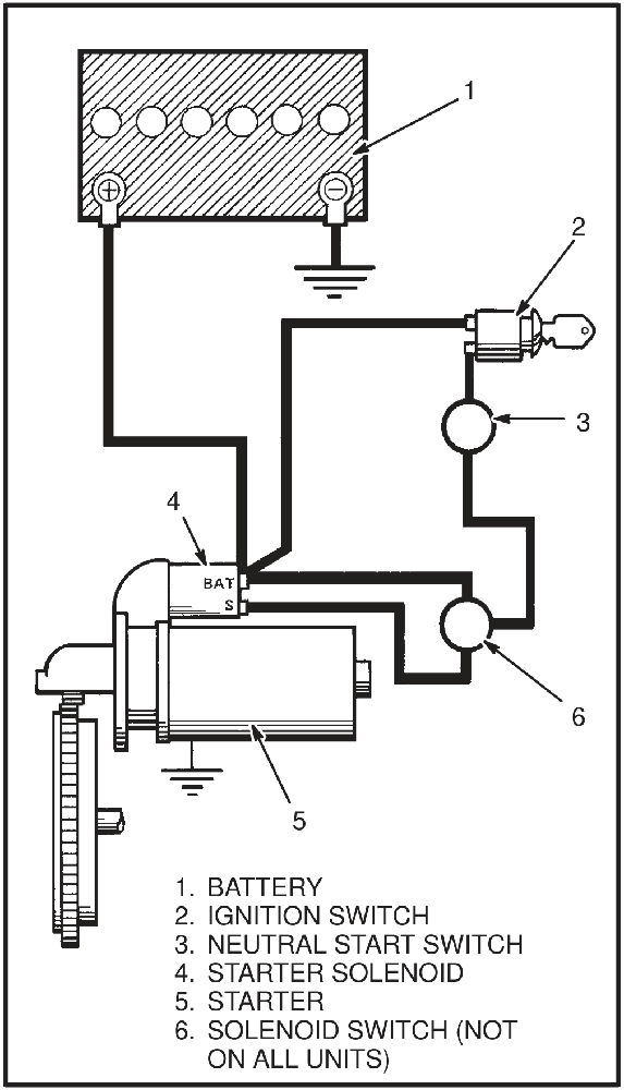
The positive battery cable lands on the "BAT" terminal of the starter solenoid, and it is live all the time. Battery voltage does not reach the starter until three switches close: the ignition switch, the transmission neutral switch, and on diesel units a solenoid switch as well. When they do, the solenoid moves the linkage and the drive clutch to engage the starter pinion with the ring gear. At the end of the plunger's stroke it closes the main solenoid contacts, current flows to the starter windings, and the pinion turns the flywheel.
The drive clutch and pinion
This is a linkage-type starter with a drive clutch mechanism. The solenoid is fastened to the starter, the pinion is part of the drive clutch, and the drive clutch slides along the armature shaft, moved by a linkage connected to the solenoid plunger.
When the engine fires, the pinion is still meshed with the ring gear. The pinion is now being driven by the engine rather than driving it, and the clutch lets it turn freely. Only when the key is released does the pinion move away from the ring gear and the starter circuit open.
Why the solenoid has two windings
The solenoid has two windings, and each does one of the two jobs.
- The pull winding draws the plunger in to close the contacts. Its current has to flow through the starter brushes to a ground.
- The hold winding keeps the plunger where the pull winding put it. Its ground is the solenoid frame.
Closing the key switch sends current through both. When the plunger has moved the linkage and the contacts close, the pull winding is short-circuited and drops out, while current keeps flowing through the hold winding. The hold winding is deenergized when the key switch is released.
The solenoid switch on diesel circuits
The solenoid switch is a relay in the diesel starter circuit, and it exists for a simple reason: a diesel starter solenoid draws more current than a gasoline one — more than is comfortable to run through the key switch. Turning the key to start actuates the solenoid switch, and the solenoid switch closes the contacts that energize the starter solenoid.
Inside the starter
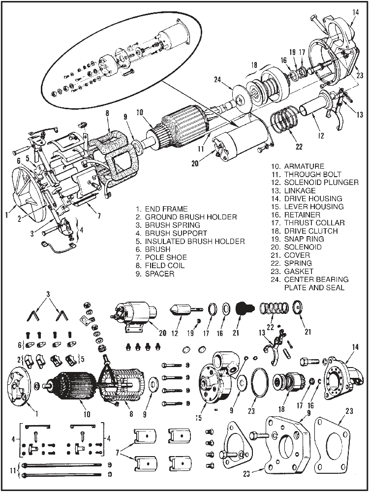
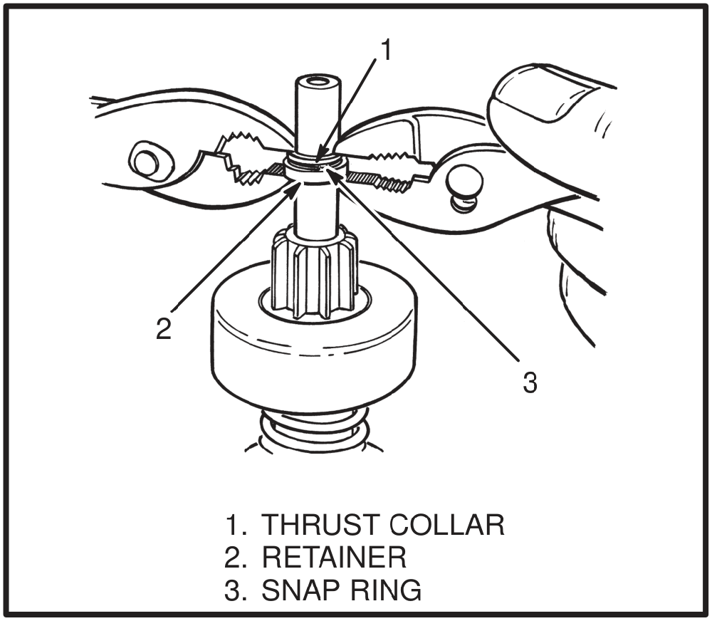
The field coils sit in the field frame behind pole shoes; the armature runs in bushings between the drive housing and the commutator end frame, held together by through bolts; four brushes bear on the commutator, carried in insulated and ground brush holders on brush supports, loaded by brush springs. On the drive end are the lever housing, the linkage, the drive clutch with its retainer, snap ring and thrust collar, and on some units a center bearing plate with a seal.
What wears out and what fails
- Brushes. Replaced once they are down to half the length of new ones.
- Commutator. Goes rough or burned. Burned bars also point at an open circuit in the armature.
- Solder connections at the commutator bars. A bad joint here shows up as a burned bar.
- Armature. Grounded or open windings, and a bent shaft.
- Field coils. Grounded or open.
- Brush springs. Lose tension, so the brushes stop following the commutator.
- Armature bushings. Wear opens up the clearance; worn bushings also show up as cables getting hot.
- Drive clutch and pinion. The pinion must turn one way and lock the other. If any part of it is damaged the complete assembly is replaced.
- Solenoid contacts. Listed as worn under the symptom where the solenoid makes noise but the starter does not turn.
- Linkage. Wears at the pivots.
- Cables and connections. Not part of the starter, but inspected, cleaned and tightened as part of the same checks.
- Seals, on units that use an oil clutch or a powershift transmission.
- Drive end housing. Checked for cracks.
Checks and tests
Always disconnect the battery ground cable before making repairs, to prevent damage and injury. Install a tag on the battery terminal so that nobody reconnects the cable while you are working.
If the starter does not operate correctly, work through these checks before taking anything apart.
Do not operate the starter for more than 30 seconds at a time, and wait at least two minutes between checks. Starters overheat quickly at cranking currents.
Before you remove the starter
- Check the battery voltage.
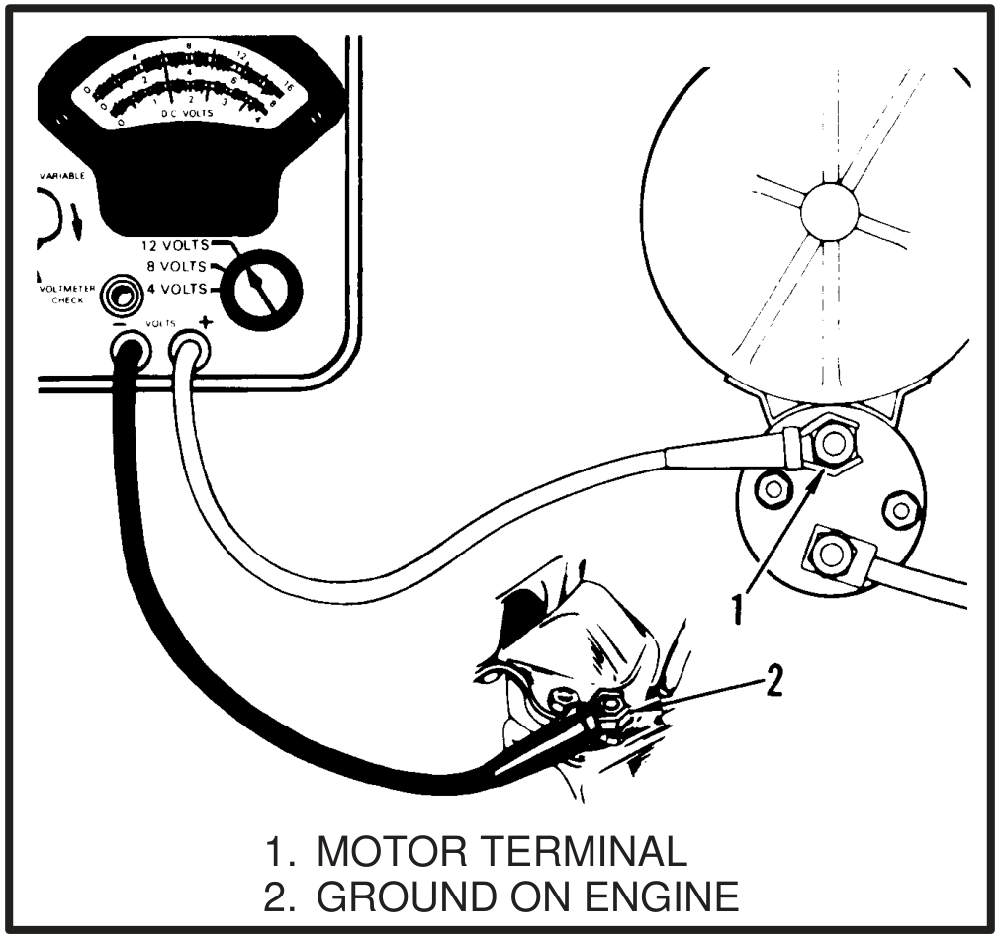
- With the key switch held in START, check the voltage at the motor terminal of the solenoid. It must be more than 9 volts.
- Inspect every connection to the battery, starter solenoid, key switch and neutral start switch. Clean and tighten as needed.
- Check the connections for resistance with a voltmeter. No single connection may show more than a 0.5 volt loss.
- Check the voltage at the "S" terminal of the solenoid. It must be more than 7 volts.
The 9 volt and 7 volt figures are absolute readings, and the source does not state the system voltage they assume. Confirm the correct thresholds for your truck's system voltage before condemning anything on the strength of them.
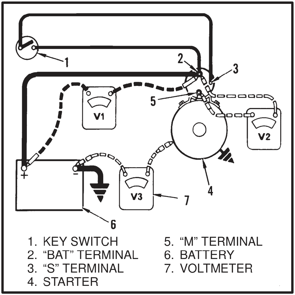
With the starter off the truck, before disassembly
- Check the ring gear on the flywheel for damage.
- Check the pinion gear on the drive clutch for damage. The pinion must turn in one direction and lock in the other. If any part has damage, replace the complete assembly.
- Check the clearance of the armature bushings.
- Check the drive end housing for cracks.
When you turn the pinion in the locked direction it moves toward the drive end housing. Do not turn it too far, or it will lock in the extended position.
With the starter dismantled
These are all ohmmeter tests, and each one is looking for a circuit that either should not exist or has gone missing.
- Armature, ground test. Touch one lead to the shaft and the other to each commutator bar in turn. If the meter shows a complete circuit, the armature is shorted to ground.
- Armature, open circuit test. Put one lead on a commutator bar and the other on the bar 180 degrees opposite. The meter must show a complete circuit. Burned commutator bars indicate an open circuit.
- Field coil, ground test. Touch one lead to the field frame and the other to the field coil brushes. On some models the field ground strap has to be disconnected first. A complete circuit means the field coils are shorted to ground.
- Field coil, open circuit test. Connect the meter across the ends of the field coils. It must show a complete circuit.
- Brush springs. Check they still have enough tension.
- Linkage. Check for wear.
- Seals, on units with an oil clutch or a powershift transmission.
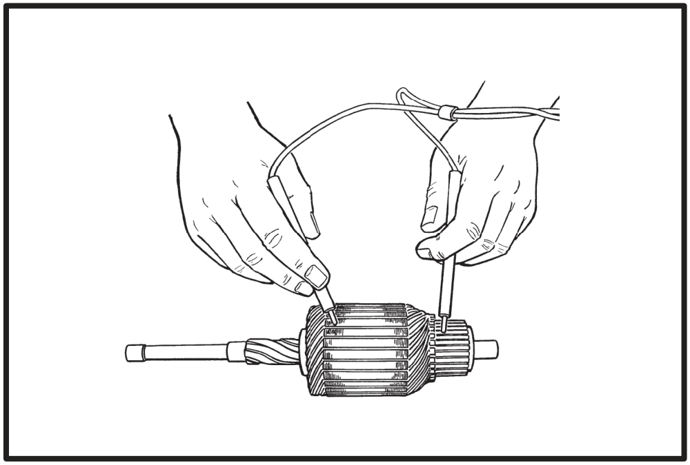
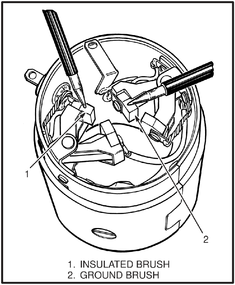
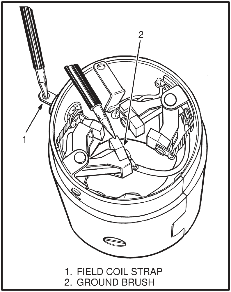
Brushes and commutator
Brushes must be at least half the length of new ones. A commutator that is rough or burned has to be skimmed in a lathe — and how much you may take off depends on how the bars are insulated from each other.
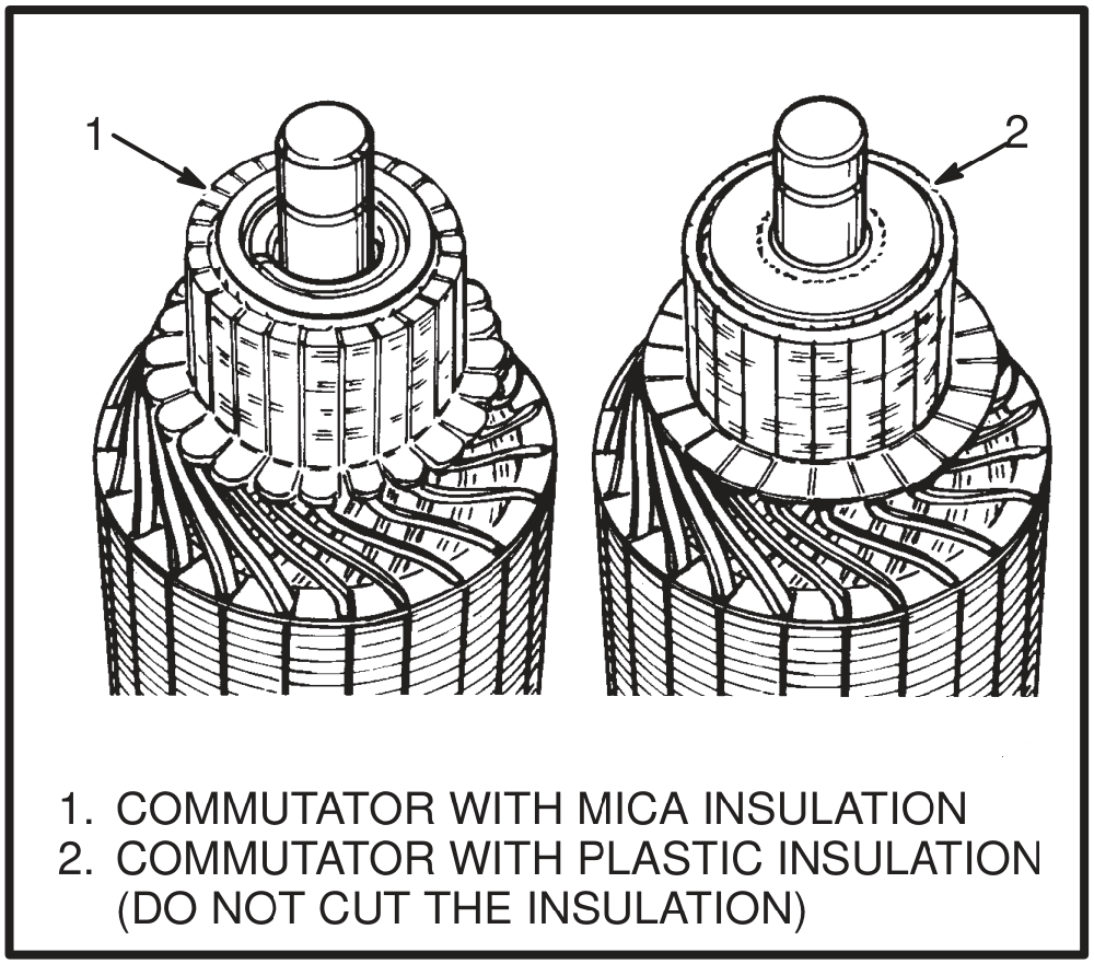
On commutators with plastic insulation, remove only enough metal to clean the surface. Do not cut the insulation between the bars. The plastic supports the bars, and because it is softer than the bars it will wear at the same rate as them in service.
Finally, check for bad solder connections at the commutator bars and resolder any that are damaged.
Cleaning
Never use solvent on the drive clutch, the armature or the field windings. Clean those with a cloth. Solvent is for the rest of the starter, and parts are dried with compressed air.
The retainer
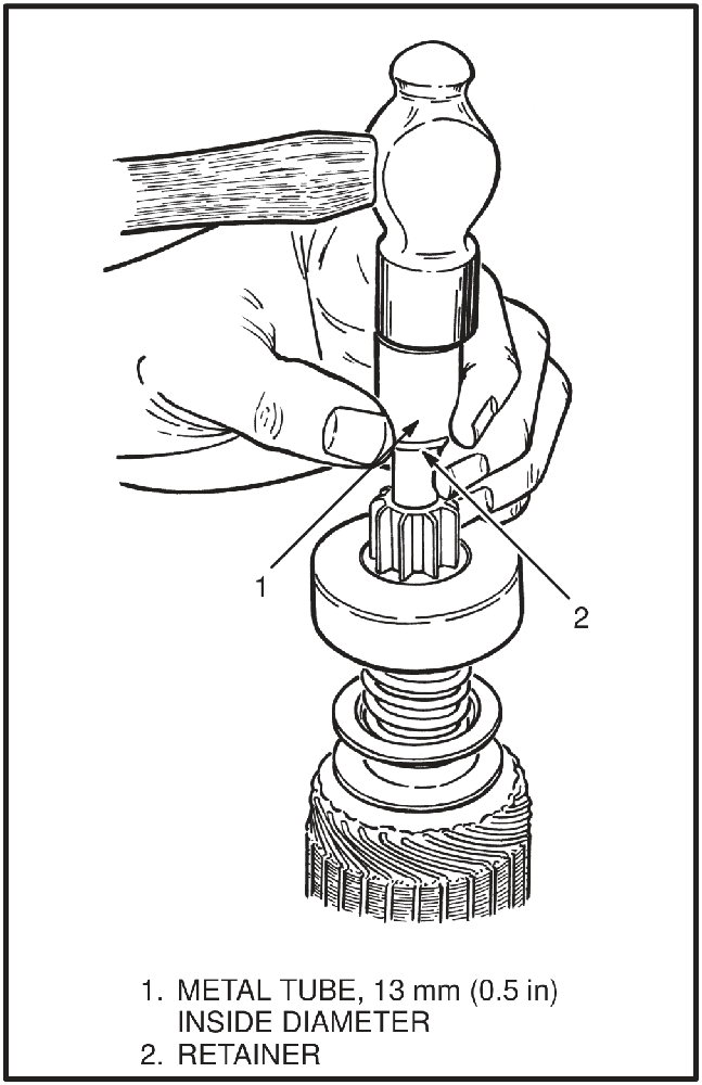
Getting the drive clutch off the armature shaft means moving a retainer that sits over the snap ring. It is driven back with a metal tube of about 13 mm (0.5 in) inside diameter, slipped over the end of the shaft and struck, which frees the snap ring for removal. On assembly the retainer is drawn back over the snap ring the other way, and the armature shaft and bushings are lubricated with a silicone lubricant.
Two other assembly details: make alignment marks on the end frame and the field frame before separating them, so they go back the same way round; and retract the brush springs to slide the brushes onto the commutator when the field frame goes back over the armature.
Troubleshooting
| Symptom | Possible cause | Procedure or action |
|---|---|---|
| Starter will not turn, no noise at the solenoid | Battery is discharged or has damageThe source lists this cause twice in this group, once with the action "Replace battery" and once with "Recharge or replace battery." Merged here. | Recharge or replace the battery. |
| A fuse is burned out | Replace the fuse. | |
| A wire in the control circuit is disconnected | Connect the wire. | |
| The key switch has damage | Install new parts. | |
| The neutral start switch has damage | Install new parts. | |
| The cable connections are bad | Install new parts. | |
| The solenoid has damage | Replace the solenoid. | |
| The starter brushes are worn or dirty | Replace the brushes. | |
| The solenoid switch has damage | Replace the switch. | |
| Starter will not turn, the solenoid makes noise | The battery is discharged or has damage | Recharge or replace the battery. |
| The starter brushes are worn or dirty | Replace the brushes. | |
| The contacts in the solenoid are worn | Install new parts. | |
| The armature circuit has damage | Repair or install new parts. | |
| The cable connections have too much resistance | Clean or install new parts. | |
| Starter will not turn, the ammeter shows a large current draw | The control circuit has a short circuit | Check the wiring for damage and repair. |
| The pinion is not engaging the ring gear | Check the clutch on the starter for damage and repair. | |
| The solenoid has damage | Replace the solenoid. | |
| The cables get too hot | The battery is discharged or has damage | Recharge or replace the battery. |
| The pinion is not disengaging from the ring gear | Check the clutch on the starter for damage and repair. | |
| The armature shaft is bent | Repair or replace the armature. | |
| The cable has a short circuit | Repair or replace the cable. | |
| The bushings are worn or damaged | Replace the bushings. | |
| The engine has damage | Repair or install new parts. | |
| The starter turns too slowly | The battery is discharged or has damage | Recharge or replace the battery. |
| The cable connections have too much resistance | Repair or install new parts. | |
| The starter brushes are worn or dirtyListed twice in this group in the source, with the same action both times. | Clean or replace the brushes. | |
| The armature circuit has damage | Repair or replace the armature. | |
| The field circuit has damageThe source prints no action beside this cause. | — | |
| The ring gear has damage | Install new parts. | |
| The engine has damage | Repair or install new parts. | |
| The ignition timing is not correct | Recalibrate the ignition timing. | |
| The starter turns, but the engine will not turn | The drive clutch has damage | Install new parts. |
| The pinion is not disengaging from the ring gearPrinted as "not disengaging" in the source, the same wording used under "the cables get too hot." | Check the clutch on the starter for damage and repair. | |
| The ring gear has damage | Install new parts. | |
| The starter makes too much noise | The solenoid has damage | Replace the solenoid. |
| The ring gear has damage | Install new parts. | |
| The drive clutch has damage | Install new parts. | |
| The battery is discharged or has damage | Recharge or replace the battery. | |
| The starter brushes are worn or dirty | Replace the brushes. |
Frequently asked questions
The solenoid clicks but the starter does not turn. What is that?
The solenoid is pulling in but something is stopping the motor from running. The listed causes are a discharged or damaged battery, worn or dirty brushes, worn contacts inside the solenoid, damage in the armature circuit, and cable connections with too much resistance. Check battery voltage, and the voltage drop across every connection.
How worn is too worn on starter brushes?
Half. The brushes must be at least one half the length of new ones. Brush spring tension is a separate check, made at the same time.
How much voltage drop is acceptable in the starting circuit?
No single connection may show more than a 0.5 volt loss when measured with a voltmeter. It is one of the checks made before the starter is removed from the truck.
Can I clean a starter in solvent?
Most of it, yes, then dry with compressed air. But never put solvent on the drive clutch, the armature or the field windings — those get wiped with a cloth.
The commutator is rough. Can I turn it in a lathe?
Yes, but check what is between the bars first. On a commutator with plastic insulation, take off only enough metal to clean the surface and do not cut the insulation between the bars. The plastic is what supports the bars, and it is softer than they are so it wears with them in service.
Why does a diesel have an extra relay in the starting circuit?
Because the solenoid on a diesel starter draws more current than the one on a gasoline starter. The solenoid switch is a relay: the key switch actuates it, and it closes the contacts that energize the starter solenoid.
Can I replace just the pinion?
No. The pinion is part of the drive clutch. Check that it turns in one direction and locks in the other, and if any part of it has damage, replace the complete assembly.
Before you order
- Brushes and brush springs. Both are checked when the starter is dismantled.
- The drive clutch is an assembly, pinion included, and it is replaced complete when any part of it is damaged.
- Retainer, snap ring and thrust collar come off during any drive clutch job.
- Solenoid contacts, listed among the wear items in the troubleshooting table.
- Armature bushings at both ends, plus the seal in the center bearing plate on units that have one.
- Gaskets and spacers between the starter and the flywheel housing, if the truck uses them.
- A sealant that forms a gasket between metal parts, where gaskets are not used.
- The solenoid switch is a separate relay on diesel circuits and is not fitted to every truck.
We stock starter motors and rebuild components: brush sets and springs, drive clutches, solenoids and solenoid switches, armatures, field coils, bushings, and the retainer and snap ring hardware. Starters manufactured outside the United States can differ internally from the design described here, so send us the number off the starter body and we will match it before you order.
This article describes a linkage-type starter with a drive clutch, of the pattern fitted to gasoline and diesel forklifts, and the checks that apply to it. Voltage thresholds, torque figures and internal details vary between makes, and starters built outside the United States can differ from this design. As above, work to the service data for your own machine. Disconnect the battery ground cable before working on the starting circuit.