

This is a general, instructive guide to how the system works and what to look for. It is not a service manual, and it is not specific to your truck. Procedures, clearances, pressures, torque figures and service limits differ between makes, models and build dates, and the manual for the machine you are actually working on is the only authority on what is correct for it. Work to that manual, and to your employer's safety procedures. The illustrations show one manufacturer's design; there are many, so read them as examples of the arrangement rather than as a picture of your machine.
How a forklift mast is built
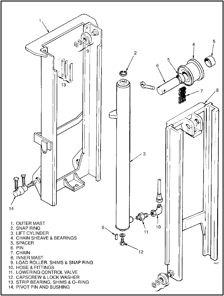
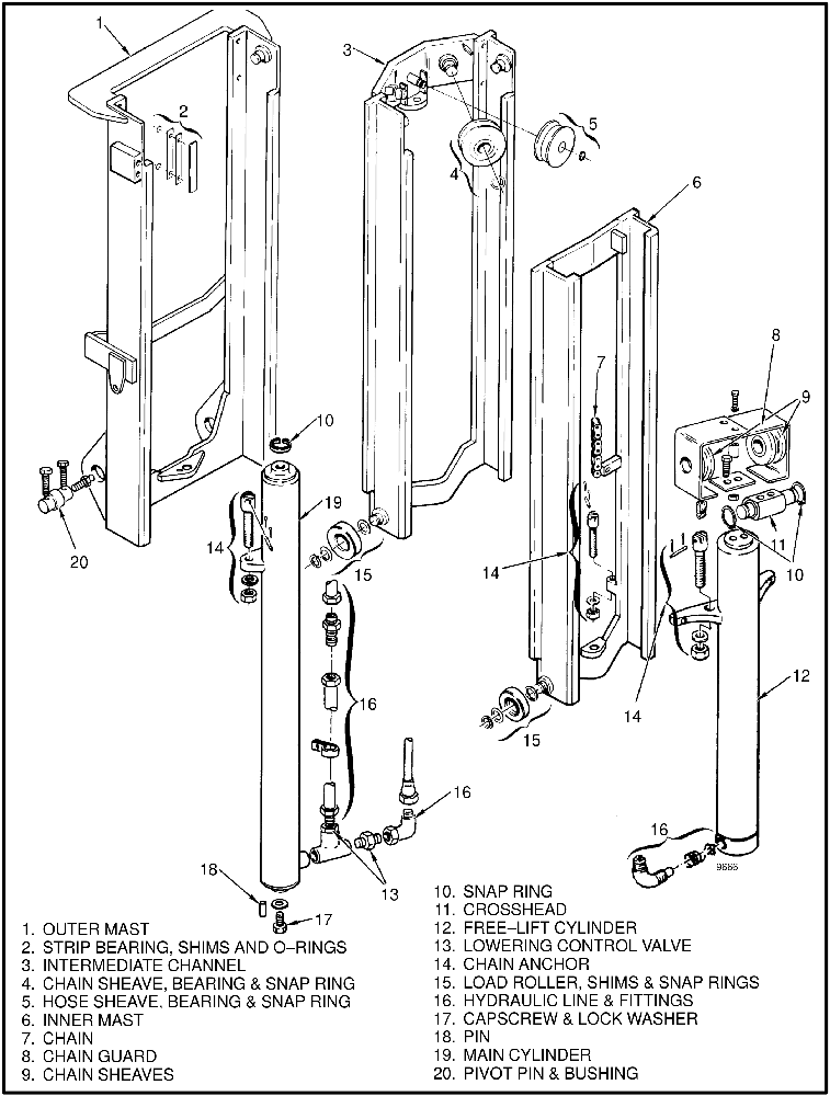
A mast is a set of steel channel weldments nested one inside another. They slide on load rollers and strip bearings, they are raised by hydraulic lift cylinders, and chains running over sheaves multiply the cylinder travel so the carriage rises faster and further than the rod itself. The carriage carries the forks and rides in the innermost weldment.
How many weldments there are is what the stage count describes, and it also determines which part moves first. On a two-stage and on a free-lift mast, the part that moves in the outer weldment is the inner weldment. On a three-stage mast it is the intermediate weldment. On a four-stage mast it is the first intermediate weldment. Free-lift and three-stage masts add a free-lift cylinder, which raises the carriage through its own travel before the main weldments move at all.
How the weldments are guided
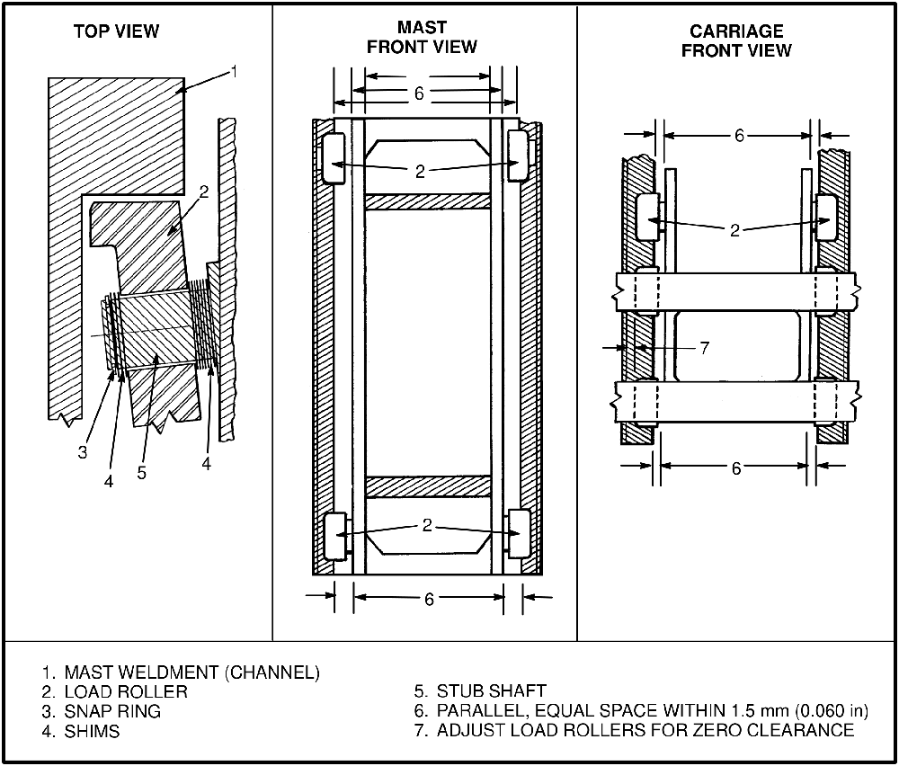
Load rollers turn on stub shafts welded to the channels, retained by a snap ring, with shims on both sides of the roller. Those shims are the adjustment: they set where the roller sits on its shaft, and so they set the clearance between the roller and the channel it runs in, and whether the weldments stay parallel. Strip bearings on the top of some channels take the load at the other end of the travel and are shimmed the same way.
The number and location of shims at each load roller and each bearing strip is recorded during disassembly, and the arrangement is rebuilt approximately the same. Clearance is then checked, and adjusted for wear or for changes made during the repair.
How the mast mounts to the truck
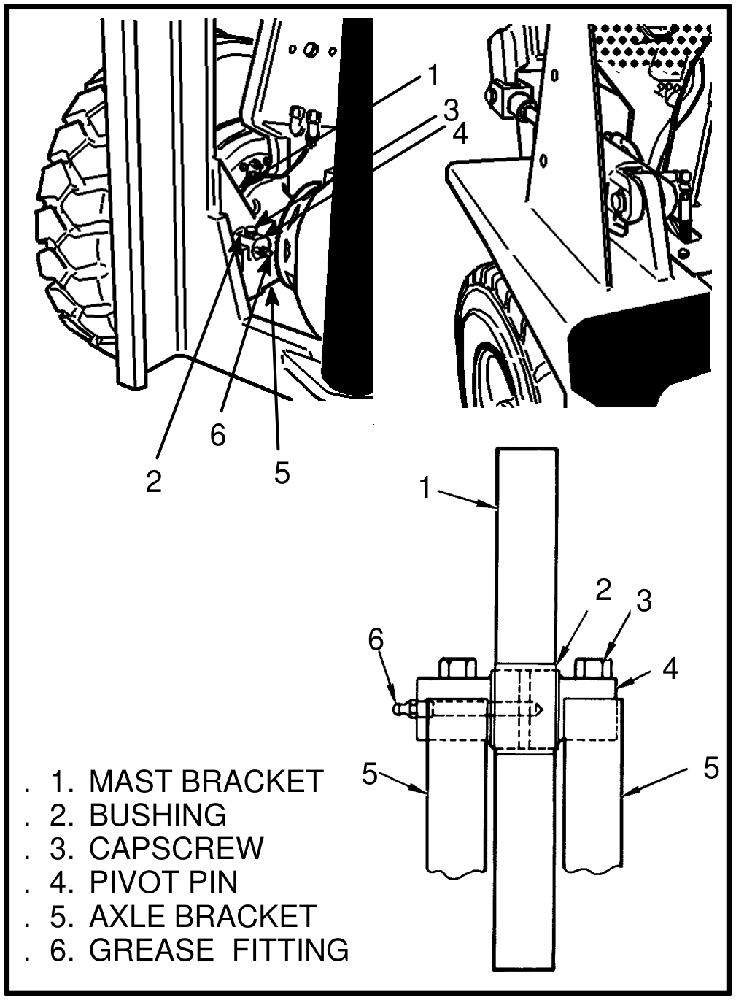
The mast pivots on pivot pins carried in bushings in the mast brackets, and the pins are held to the axle brackets by capscrews. Grease fittings serve the pivots, and they face toward the center of the mast. Tilt cylinders connect to the mast through a clevis and pin at each side; tilting the mast is what these cylinders do, and their stroke is what sets the tilt angle.
Working safely near a mast
Mast parts are heavy and they can move. The distances between parts are small. Serious injury or death can result if part of the body is hit by parts of the mast or the carriage. Never put any part of the body into or under the mast or carriage unless all parts are completely lowered, or a safety chain is installed. Make sure the power is off and the key is removed, and put a "DO NOT OPERATE" tag in the operator's compartment.
The rule is simple: everything down, or everything chained. Lower the mast and carriage completely, push the lift and lower control lever forward, and confirm there is no movement and that every part of the mast that moves is fully lowered.
Do NOT use blocks to support the mast weldments, and do not use blocks to restrain their movement. Do NOT climb on the mast or the lift truck at any time — use a ladder or a personnel lift. When the mast is raised, the forks can be at a height to cause an injury.
Restraining a raised mast
If parts of the mast have to stay raised, they are restrained by chaining the moving part to a part that does not move.
- Put the mast in a vertical position.
- Raise the mast to align the bottom crossmember of the weldment that moves with a crossmember on the outer weldment.
- Use a safety chain of at least 3/8 inch, with a hook, to fasten the crossmembers together so the movable member cannot lower. Put the hook on the back side of the mast, and make sure it is completely engaged with a link in the chain. The safety chain must not touch lift chains, chain sheaves, tubes, hoses, fittings or any other part of the mast.
- Lower the mast until there is tension in the safety chain, and until the free-lift cylinder is completely retracted on masts that have one. Stop the engine, apply the parking brake, and install a "DO NOT REMOVE" tag on the safety chain.
- Install a second safety chain, also 3/8 inch minimum, between the top or bottom crossmember of the carriage and a crossmember on the outer weldment.


Lifting and rigging
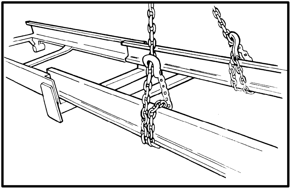
The crane, slings and chains used to lift mast assemblies must be rated for at least 2,000 kg (4,400 lb). When a mast is connected to a crane, chains go around all the top crossmembers of the channels, the crane sits centered above the mast, and the chains are raised only until they are not loose — the mast is not lifted at that stage. The chains must not damage the sheaves or other mast parts.
When weldments are separated, each channel piece is chained near its center of gravity with the chain passed around the piece twice and pulled tight, so the weldment cannot slide in the chain. The crane supports the weldment without lifting it, stays directly over the chains, and the weldment is not allowed to tilt. The stub shafts are easily damaged and are protected throughout.
When disconnecting lift chains, control the ends. An uncontrolled chain can roll over the sheaves and fall, causing injury and damage. Do NOT use your fingers to push the pins out of the clevis of a tilt cylinder rod — use a driver. Never allow anyone under a raised carriage.
The carriage, forks and attachments
Hook forks
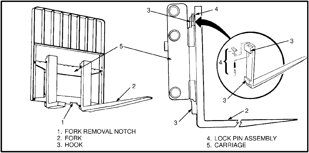
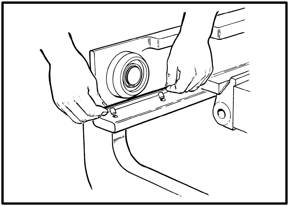
A fork is identified by how it connects to the carriage. Hook forks hang on the carriage bars by an upper and a lower hook, and a lock pin through the top fork hook drops into a slot in the top carriage bar to hold the fork at the width you set. To reposition a fork, raise its lock pin, slide the fork along the bar, and make sure the pin re-engages a notch in the carriage bar afterwards. Set the forks as far apart as the load allows, for maximum support.
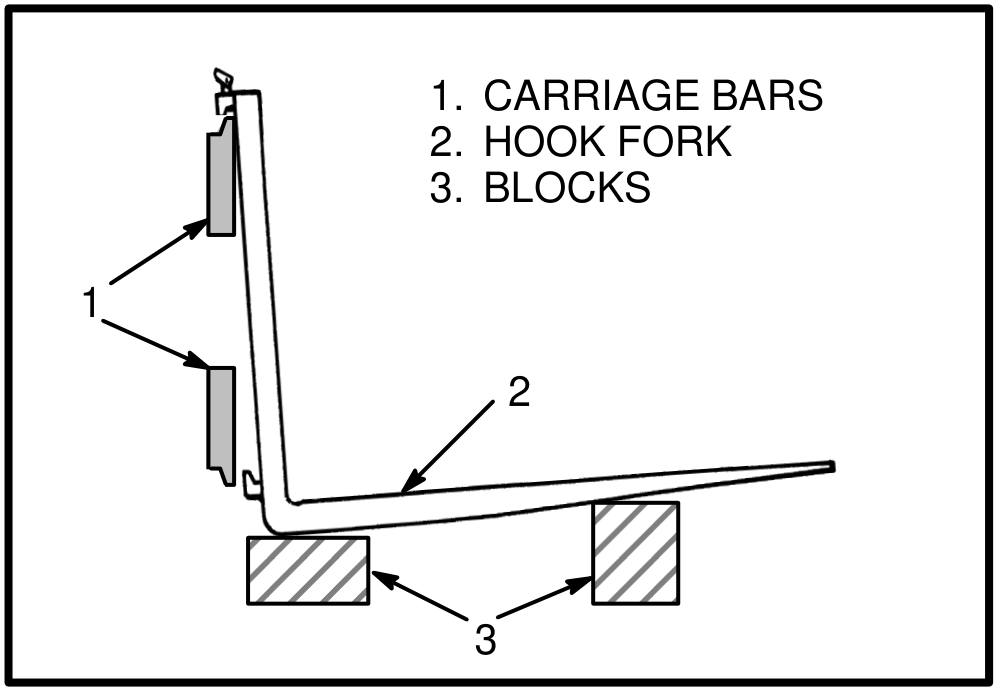
Forks come off through a removal notch in the bottom crossmember of the carriage. Slide the fork to the notch, lower the fork onto blocks so the bottom hook passes through the notch, then lower the carriage further until the top hook is clear of the top carriage bar. Installation reverses that: engage the top hook on the upper bar, raise the carriage to bring the lower hook through the notch, slide the fork along so both hooks engage, and re-engage the lock pin.
Do not try to move a fork without a lifting device. A hook fork of this type can weigh 45 to 115 kg (100 to 250 lb).
Side-shift carriages
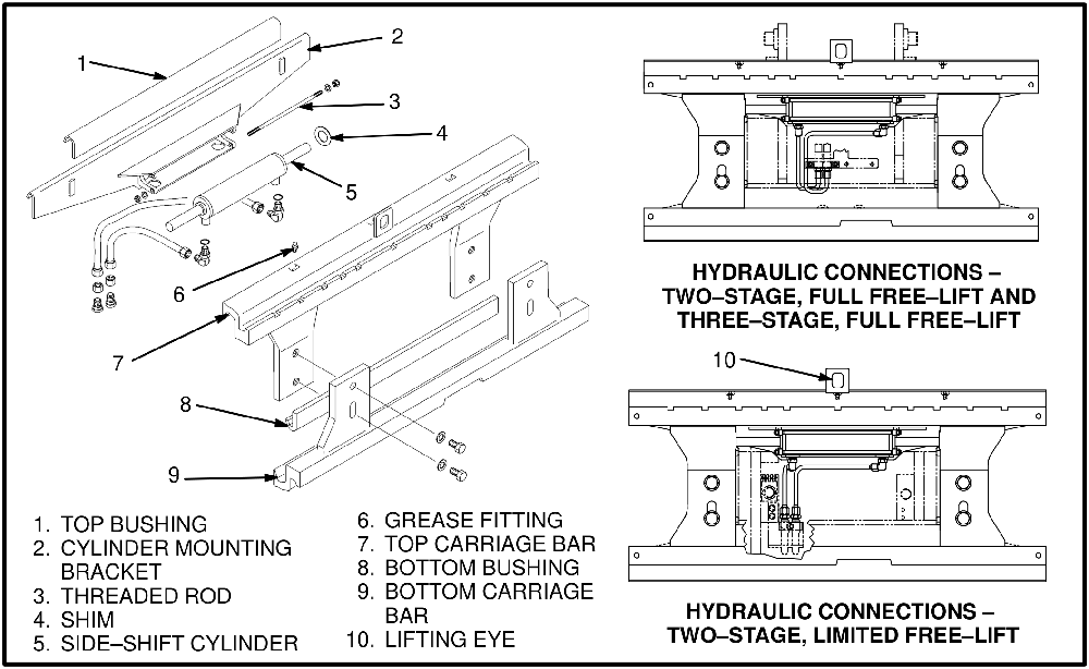
A side-shift carriage adds an apron that slides across the carriage on bushings, driven by a hydraulic side-shift cylinder mounted to a bracket on the carriage. The apron hangs on the top carriage bar and is retained at the bottom by two carriage hooks; shims and a threaded rod set the cylinder mounting, and grease fittings serve the bushings. A lifting eye is provided.
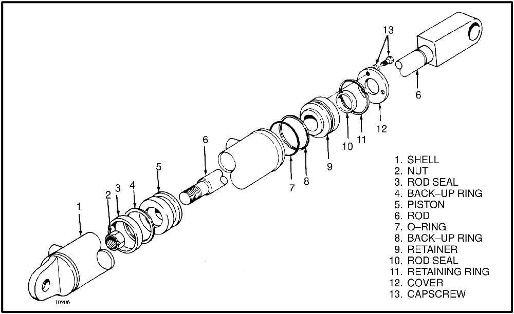
The side-shift cylinder is the only item in a side-shift carriage that normally needs repair. It is a rod-and-piston cylinder: shell, piston and rod, retainer and cover, with rod seals, an O-ring and back-up rings. Servicing it means removing the cover capscrews and retaining ring, drawing the rod and piston assembly out of the shell, and renewing the seals, O-rings and back-up rings as needed, with everything lubricated in clean hydraulic oil on reassembly.
Header hoses
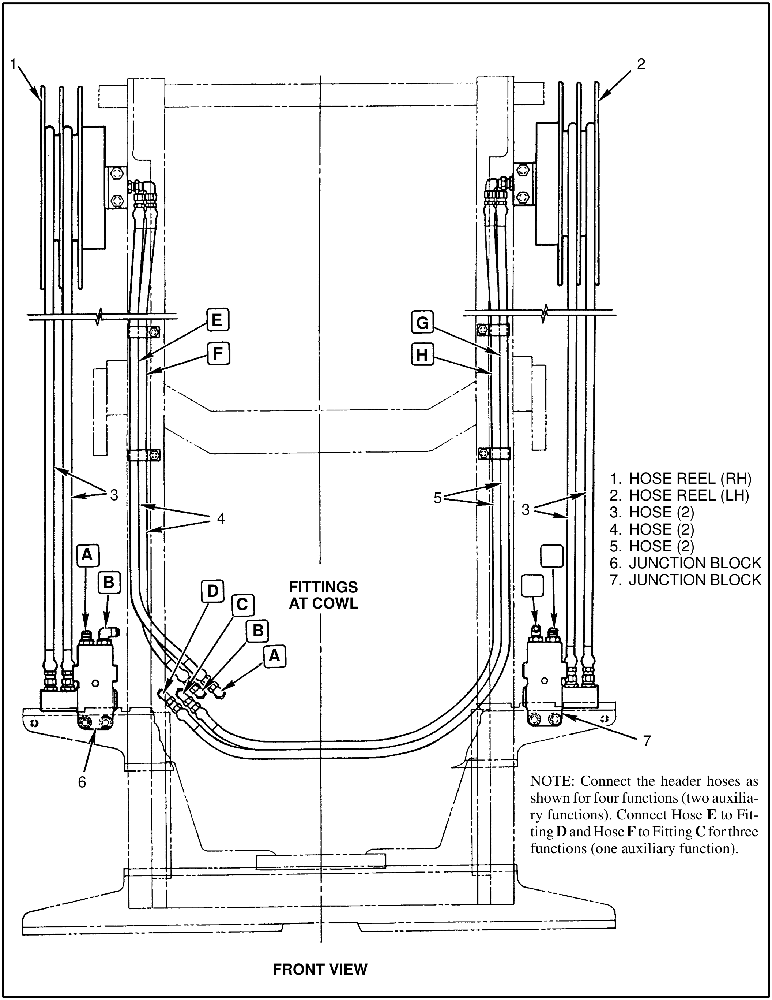
Trucks equipped for auxiliary hydraulic functions — side-shift carriages, roll clamps and similar attachments — need header hoses routed up the mast, in either one pair or two pairs. On a three-stage mast each auxiliary function needs a hose reel, and the reel carries a spring that keeps the hoses tight. These arrangements do not normally need adjustment after removal and installation. When header hoses are installed, the reel is wound three turns for correct tension: a right-hand reel clockwise, a left-hand reel counterclockwise.
A hose reel has a strong spring, and the spring is compressed inside the reel even when the reel is unwound. Keep the hoses under control when disconnecting them at the carriage. Never disassemble a hose reel without complete knowledge of the manufacturer's recommended procedures.
What wears out and what fails
- Load rollers and sheaves. Inspected for wear or damage. The bearings inside them are sealed and lubricated, so they are not serviced separately.
- Strip bearings. Wear opens up the clearance at the top of the channels and is taken up with shims.
- Lift chains. Stretch, and the seven defects covered in the next section.
- Chain anchors and pins. Inspected and replaced if worn or damaged.
- Sliding surfaces and load roller contact surfaces on the channels, inspected for wear or damage.
- Welds. Inspected for cracks — and see the warning below about what you may not do about them.
- Cylinder seals. Internal leakage in the lift or tilt cylinders shows as drift, which is measurable; see Checks and adjustments.
- Side-shift cylinder seals, O-rings and back-up rings, the normal repair item on a side-shift carriage.
Do NOT weld on the mast. The strength of the mast can be reduced by welding or by heating. Get information from the truck manufacturer or your dealer before welding on a mast.
Lift chain inspection and wear
A lift chain becomes longer when it is worn. That is what chain condemnation measures, and it is why twenty links are measured rather than one.
Clean the chains with solvent and inspect them. If a chain is 3% longer than a new chain, it must be replaced. A chain wear scale reads this directly. Without one, measure twenty links and compare against the length for that pitch. Lubricate with SAE 30 engine oil after cleaning.
Never replace just the worn section of a chain — replace the complete chain. Never replace just one chain of a chain pair — replace both.
| Chain pitch | 20 links, new | Replace at (3% longer) |
|---|---|---|
| 12.7 mm (0.50 in) | 254.0 mm (10.0 in) | 261.6 mm (10.3 in) |
| 15.9 mm (0.625 in) | 317.5 mm (12.5 in) | 327.0 mm (12.88 in) |
| 19.1 mm (0.75 in) | 381.0 mm (15.0 in) | 392.4 mm (15.45 in) |
| 25.4 mm (1.00 in) | 508.0 mm (20.0 in) | 523.25 mm (20.6 in) |
| 31.8 mm (1.25 in) | 635.0 mm (25.0 in) | 654.1 mm (25.75 in) |
| 44.5 mm (1.75 in) | 889.0 mm (35.0 in) | 915.7 mm (36.05 in) |
| 50.8 mm (2.00 in) | 1016.0 mm (40.0 in) | 1046.5 mm (41.2 in) |
Every row above is internally consistent: twenty links of a given pitch give the new length exactly, and the replace-at figure is exactly 3% more. Confirm the pitch of your own chain before measuring, and work to the service data for your truck.
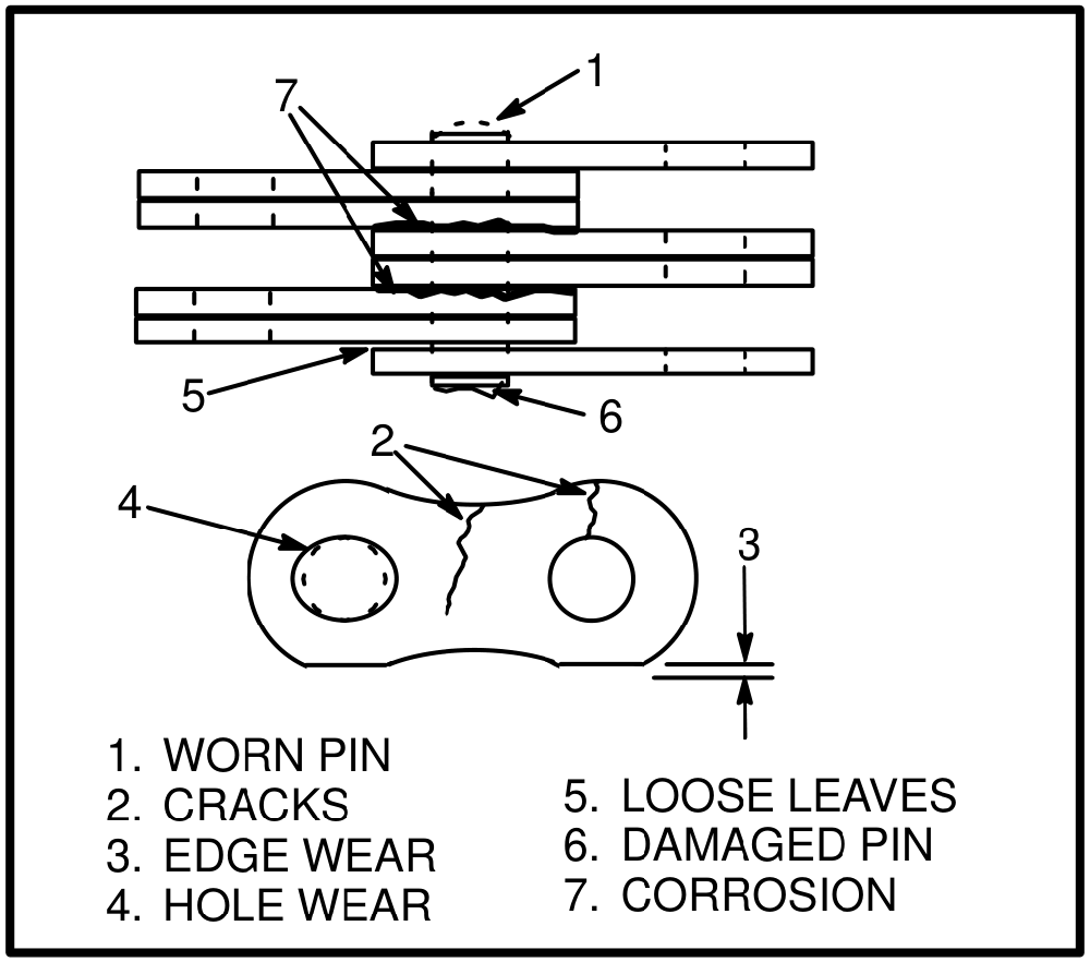
Length is not the only reason to condemn a chain. Inspect for a worn pin, cracks, edge wear, hole wear, loose leaves, a damaged pin and corrosion.

Do NOT use steam to clean lift chains, sheaves or load rollers — the bearings in the sheaves and load rollers are sealed and lubricated. Steam can also cause serious burns; wear protective clothing and gloves and never expose skin to it. Commercial cleaning solvents may be flammable and toxic and can cause severe skin irritation, so follow the solvent manufacturer's safety precautions.
Checks and adjustments
Load roller and strip bearing clearance
The load rollers control the alignment of the mast weldments. Three conditions are given, most important first:
- The vertical channels must be parallel to each other, to decrease wear.
- The maximum clearance between the load roller and the channel, at the tightest fit, is 0.8 mm (0.030 in).
- The number of shims under a load roller must be approximately the same as at the stub shaft on the opposite side of the weldment, so the weldments sit approximately central.
Shims go on both sides of the load roller. To move a roller on its shaft you move shims from one side to the other rather than adding or removing them from the stub shaft. Clearance is found by moving the weldments side to side with a prybar and measuring the movement, repeated in at least three different positions, and by sliding a weldment all the way to the top and to the bottom to find the tightest fit. Shims are then changed until the tightest fit is within 0.8 mm (0.030 in), and the distance between the channels is kept equal top and bottom, with the weldments parallel within 1.5 mm (0.060 in).
Strip bearings are adjusted the same way, with shims inserted between the strip bearing and the channel, to the same 0.8 mm (0.030 in) maximum clearance at the tightest fit.
Carriage load rollers
The carriage rollers are installed with their shims in the same sequence on the stub shaft as before disassembly, and no shims go under the top load rollers. The carriage is raised up the inner mast on a crane to find the tightest fit, then removed so the shim arrangement can be corrected. Maximum clearance between roller and inner mast is 0.5 mm (0.020 in) at the tightest fit, the shim arrangement is kept approximately equal on each side, and the carriage must be parallel with the inner mast channel within 1.5 mm (0.060 in).
After adjustment, lubricate the channels with a thin layer of grease. Too much grease will cause the rollers to slide instead of roll, and wear flat areas on them.
Lift chain adjustment
When the lift chains are correctly adjusted, the tension is the same on each chain of the set, the chain length is correct, and the chains travel freely through the complete cycle. Check tension by pushing on both chains at the same time.
With the mast vertical, the chains at the carriage are adjusted at the chain anchors so that the lower edge of the bottom carriage bar sits 82.5 mm (3.25 in) above the floor. On a three-stage mast the main lift chains are adjusted first, at the anchors on the main lift cylinders, so the top of the inner weldment is even with the top of the outer weldment within 1.5 mm (0.06 in); the carriage chain is then set as above.
When the adjustment is finished, the threads on the chain anchor nuts must be completely engaged, and not all of the adjustment may be used up — a minimum of two times the thread diameter must remain available, and the anchors must still be able to move in their sockets. Finally, lower the mast completely, put a capacity load on the forks, tilt fully backward, and check how far the bottom carriage load roller extends below the inner channel.
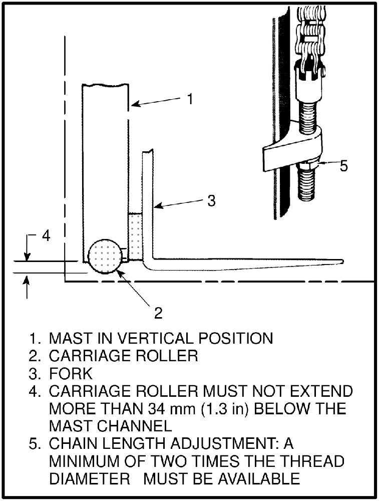
The source gives two different criteria for how far the bottom carriage roller may extend below the channel: the text says no more than one third of the roller will be visible when the adjustment is correct, and the figure says the roller must not extend more than 34 mm (1.3 in) below the mast channel. It does not reconcile them. Treat whichever is stricter for your roller diameter as the limit, and confirm against the service data for your truck.
Tilt cylinder stroke and backward tilt angle
Tilt the mast slowly, fully forward and fully backward, several times. Both tilt cylinders must stop their stroke at the same time, and there must be no twist in the mast weldments. Tilt fully backward and measure the tilt angle against the figure on the truck's nameplate.
The cylinder that stops last when tilting backward needs a shorter rod adjustment; the cylinder that stops last when tilting forward needs a longer one. Rod length is changed by loosening the rod end and turning the cylinder rod, and both cylinders must finish with the same stroke. The tilt angle itself is then set by adjusting the cylinder rod as necessary. Tighten the capscrews on the rod ends once the stroke and the angle are both correct. If the truck is fitted with tilt limit spacers, make sure they are installed.
Checking for hydraulic leakage
During these tests, use chains to fasten the load to the carriage so it cannot fall, and keep all personnel away from the lift truck.
External leaks. With an 80 to 90% capacity load on the forks, raise and lower it several times, then lower the load and tilt the mast forward and backward several times. Look for leaks.
Internal leakage in the lift system. With a capacity load on the forks, raise the carriage until the mast is fully extended and put the control valve in neutral. If the carriage lowers slowly there is internal leakage. Typical limits are 33 mm (1.3 in) of drop in 10 minutes with the hydraulic oil at 30 °C (86 °F), rising to 146 mm (5.8 in) in 10 minutes at 60 °C (140 °F) — oil temperature matters as much as the reading.
Isolating the lift cylinder. Install a gate valve in the supply line between the main control valve and the lift cylinder. With an 80 to 90% capacity load, raise the carriage until all the weldments are extended, then close the gate valve. If the carriage or the weldments still lower slowly, the leak is in the lift cylinder seals rather than upstream.
Internal leakage in the tilt system. Tilt the mast forward by a small amount with an 80 to 90% capacity load, then return the valve to neutral. If the mast continues to tilt slowly forward there is an internal leak. Typical limits are 11 mm (0.4 in) of rod extension in 10 minutes at 30 °C (86 °F), and 50 mm (2.0 in) in 10 minutes at 60 °C (140 °F).
Tilt cylinder piston seals. Tilt the mast fully forward, disconnect the hydraulic line from the front of the tilt cylinder and leave the cylinder port open, capping the disconnected line. Operate the hydraulics to tilt the mast against the forward stops. Leakage from the open cylinder port means the piston seals are leaking.
Troubleshooting
| Symptom | Possible cause | Procedure or action |
|---|---|---|
| No movement of the lift or tilt cylinders | Linkage at the control valve is disconnected | Connect and adjust the linkage. |
| No oil, or not enough oil, in the hydraulic tank | Fill the tank. Check for leaks. | |
| Relief valve is not set correctly | Adjust the relief valve or install a new one. | |
| Hydraulic pump does not operate, or has damage | Repair the pump or install a new one. | |
| Slow movement of the lift or tilt cylinders | No oil, or not enough oil, reaching the lift cylinders | Fill the tank. Check for leaks. |
| Cylinders have internal or external leaks | Repair the leaks. Install new parts. | |
| Relief valve is not set correctly | Adjust the relief valve or install a new one. | |
| There is a restriction in a hydraulic line | Remove the restriction. Install new parts. | |
| Load is more than capacity | Reduce the load. | |
| Hydraulic control linkage is incorrectly adjusted | Adjust the linkage. | |
| Rough movement of the mast assembly | There is air in the hydraulic system | Remove the air. Check for loose connections or breaks in the lines. |
| Lift cylinder is damaged | Repair the lift cylinder or install a new one. | |
| Mast weldments are damaged or not aligned | Align the weldments. Install new parts. | |
| Mast weldments are not lubricated correctly | Correct the lubrication. | |
| Lift or tilt cylinders extend or retract with the control valve in NEUTRAL | Load check valves and spools have damage | Repair the load check valve and spool, or install new ones. |
| Cylinder seals have leaks | Install new seals. | |
| Hydraulic lines have leaks | Repair the leaks. Install new parts. | |
| Leaks between the spool and the boreThe source table prints one further action here, "Remove air from the system," on a line with no cause printed beside it. | Install a new spool and O-ring seals. |
Frequently asked questions
Can I use blocks to hold the mast up while I work on it?
No. Blocks must not be used to support the mast weldments, and must not be used to restrain their movement. Either lower the mast and carriage completely, or restrain the moving parts with a safety chain of at least 3/8 inch fastened between a crossmember on the moving weldment and one on the outer weldment.
How do I know when a lift chain is worn out?
By length. A lift chain gets longer as it wears, and once it is 3% longer than a new chain it must be replaced. A chain wear scale reads this directly against the chain. Without one, measure twenty links and compare with the figure for your chain's pitch in the table above.
Can I replace just the worn section, or just the one chain that is stretched?
Neither. Replace the complete chain, never just the worn section. And never replace only one chain of a pair — both chains are replaced together.
The carriage creeps down with the lever in neutral. Is that normal?
Some drift is expected and it is measurable rather than pass-or-fail. With a capacity load and the mast fully extended, typical limits are 33 mm (1.3 in) in 10 minutes with the oil at 30 °C, and 146 mm (5.8 in) in 10 minutes at 60 °C. To find out whether the lift cylinder or something upstream is responsible, fit a gate valve between the main control valve and the cylinder and close it during the test.
Can I weld up a crack in the mast?
Do not weld on the mast. The strength of a mast can be reduced by welding or by heating it. Inspect the welds for cracks as part of any overhaul, but get information from the truck manufacturer or your dealer before any welding is done on a mast.
Why are there shims at every load roller, and what happens if I lose track of them?
The shims set where each roller sits on its stub shaft, which sets the roller-to-channel clearance and keeps the weldments parallel and centered. Note the number and location at each position during disassembly, because the arrangement is rebuilt approximately the same. To move a roller, shift shims from one side of it to the other rather than adding or removing them at the stub shaft, then re-check the clearance.
Can I steam clean a mast?
The weldments, yes — steam or solvent. But do not use steam on the lift chains, the sheaves or the load rollers. The bearings in the sheaves and load rollers are sealed and lubricated, and the chains are cleaned with solvent and re-lubricated with SAE 30 engine oil.
Before you order
- Load rollers come with their shims and snap ring. The shim pack is part of the fit, not packaging — keep the old ones as a reference until the new clearance is set.
- Strip bearings come with shims and an O-ring.
- Sheaves come with their bearings and snap ring. The bearings are sealed and lubricated and are not serviced separately, so a rough sheave is a sheave assembly.
- Chains are ordered in pairs and in complete lengths. Never a section, never one side of a pair. Know your pitch before ordering.
- Chain anchors and pins are separate wear items from the chain itself and are inspected at the same time.
- New cotter pins whenever chains are reinstalled.
- Side-shift carriages are usually a seal job: rod seals, O-ring and back-up rings for the cylinder.
- Pivot pins, bushings and grease fittings for the mast mounting.
- Hose reels are not a rebuild item without the reel manufacturer's procedure — the spring stays compressed even when the reel is unwound.
We stock lift chains by pitch, chain anchors and pins, load rollers, strip bearings and shim packs, sheaves and bearings, seal kits for lift, tilt and side-shift cylinders, hook forks and lock pins, and mast pivot pins and bushings. If you are not sure of your chain pitch or roller size, send us the truck's serial number and we will identify it before you order.
This article describes how a nested-weldment forklift mast with a hook carriage is built, what wears in it and how it is checked. The source covers the standard two-stage and three-stage masts; four-stage masts appear only in the safety procedure. Clearances, chain datums, tilt angles and torque figures vary between trucks and mast types. As above, work to the service data for your own machine. Follow the safety procedure before any part of you goes near a mast.