

This is a general, instructive guide to how the system works and what to look for. It is not a service manual, and it is not specific to your truck. Procedures, clearances, pressures, torque figures and service limits differ between makes, models and build dates, and the manual for the machine you are actually working on is the only authority on what is correct for it. Work to that manual, and to your employer's safety procedures. The illustrations show one manufacturer's design; there are many, so read them as examples of the arrangement rather than as a picture of your machine.
How an LPG fuel system works
An LPG fuel system stores fuel as a liquid under pressure, releases it into a vaporizer that changes it to a gas, then meters that gas against the air entering the engine. The system is made up of a fuel tank, a hydrostatic relief valve, a filter with a fuel valve, a vaporizer, a carburetor and a governor.
Liquid fuel leaves the tank and travels to the filter unit, which contains a fuel valve. From the filter unit the liquid enters the vaporizer. The vaporizer changes the liquid to a low-pressure vapor and passes it to the carburetor, and from the carburetor the air and fuel mixture goes through the governor to the intake manifold. Three supporting connections make the system work: engine coolant circulates through the vaporizer, inlet manifold vacuum operates the fuel valve in the filter unit, and a balance line connects the carburetor to the vaporizer.
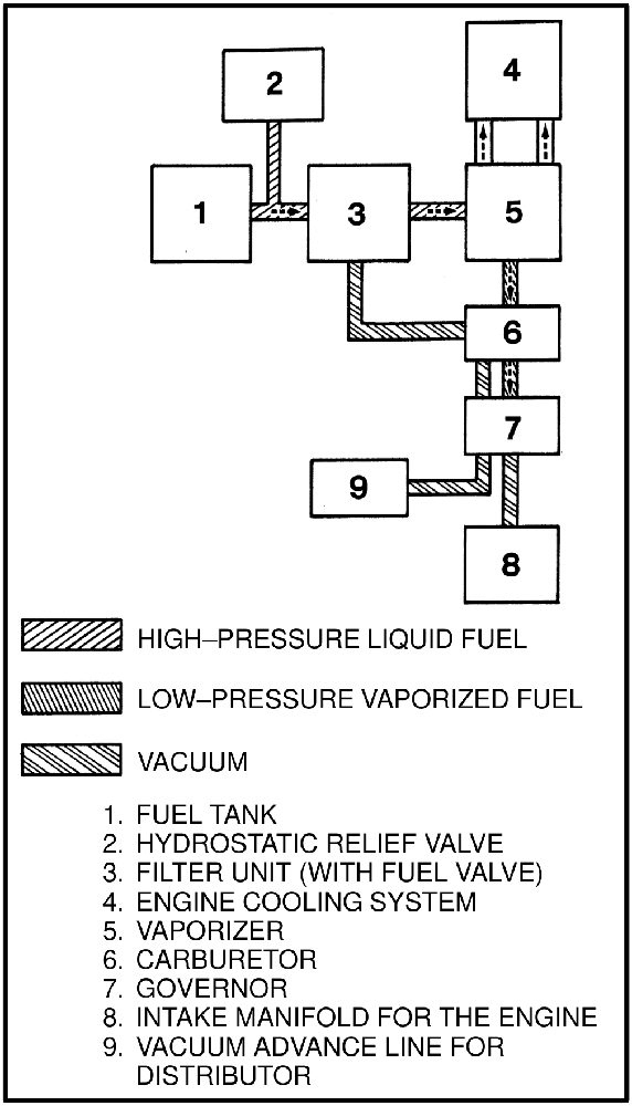
The fuel tank
The tank is the reservoir for the system, and it keeps the fuel in the liquid condition. It has a pressure relief valve, and the inlet tube for that valve sits in the vapor area at the top of the tank.
A fuel gauge measures the percentage of fuel in the tank. Near the pressure relief valve there is a liquid level valve, which is used to indicate the maximum liquid level that is permitted — the tank is filled until liquid fuel flows from that valve.
Inside the tank, one end of the outlet tube is near the lower surface of the tank and the other end is fastened to the outlet port. A shut-off valve is connected to the outlet port and can prevent fuel from leaving the tank when the outlet line is disconnected. A quick disconnect fitting is installed so the tank can be removed easily.
The tank has a guard for the valves and fittings, and that guard has a hole for the alignment dowel on the mount. Metal straps with latches fasten the tank to the truck. A fuel pressure sensor in the line from the tank energizes an indicator light on the instrument panel when the tank is nearly empty and the fuel pressure decreases.
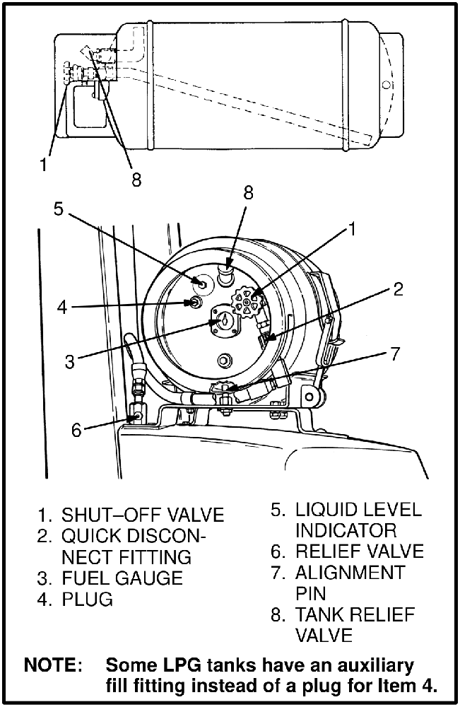
The valve face of the tank typically carries a shut-off valve, a quick disconnect fitting, a fuel gauge, a plug, a liquid level indicator, a relief valve, a tank relief valve, and the alignment pin that sets the tank's rotational position in the bracket.
Some tanks have an auxiliary fill fitting in place of the plug.
The filter unit and fuel valve
A fuel line connects the tank to the filter. The filter prevents dirt from entering the vaporizer, and it houses a fuel valve that is operated by engine vacuum. That valve prevents fuel from entering the vaporizer unless the engine is being started or is running.
Inside the unit, a leaf spring holds a polyurethane pad against a seat. A diaphragm opens the valve. Air pressure pushes on the vent side of the diaphragm; the other side sees inlet manifold vacuum and carries a lever and plunger that open the valve. When the engine starts, the air pressure on the lever side of the diaphragm decreases. Air pressure on the vent side then moves the diaphragm, lever and pin, lifting the valve pad off its seat, and liquid LPG flows through to the vaporizer.
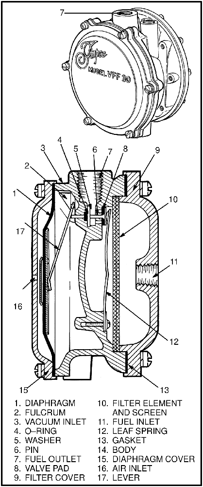
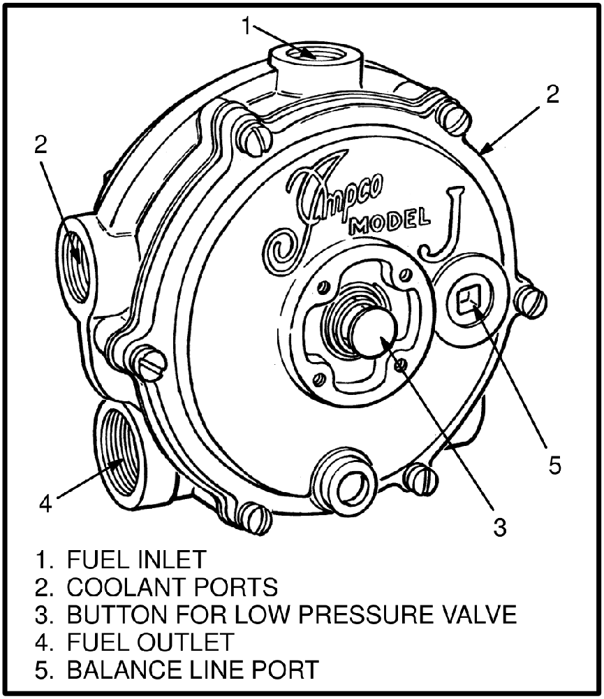
The vaporizer
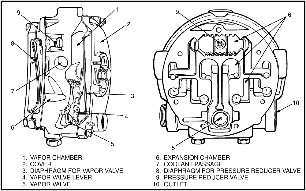
The vaporizer has two jobs: change the liquid fuel to a vapor, and control the pressure of that vapor.
A liquid needs heat to change to a gas. When the pressure of the liquid LPG is quickly decreased inside the expansion chamber, heat is removed from the vaporizer. The vaporizer therefore has to be heated by engine coolant to replace the heat that is lost to the fuel, and coolant passages inside it prevent the vaporizer from becoming too cold to operate.
Liquid fuel enters the vaporizer inlet from the filter unit. The pressure reducer valve has a polyurethane pad and a seat; while the pad is against the seat, liquid fuel cannot enter the expansion chamber. When liquid does enter through the pressure reducer valve, the pressure of the fuel pushes on the diaphragm, and the diaphragm immediately moves and closes the valve. Because only a very low pressure is needed to close that valve, the fuel pressure in the expansion chamber stays very low. The sudden decrease in pressure is what changes the fuel from a liquid to a vapor, and the change takes heat from the surfaces of the expansion chamber. Warm coolant flows next to those surfaces to replace the heat.
The vapor is held in the expansion chamber by the vapor valve. When the engine starts, gas in the vapor chamber leaves to flow through the carburetor, so the pressure on the vapor diaphragm decreases. Air pressure on the other side of that diaphragm then pushes it and opens the vapor valve. Gas flows from the expansion chamber to the vapor chamber and on to the solenoid valve and the carburetor. The pressure in the expansion chamber decreases and the pressure reducer valve opens again to repeat the operation. When the carburetor throttle is closed, the vacuum in the vapor chamber decreases and the vapor valve closes.
A button in the vaporizer housing can be used to open the vapor valve manually, which sends LPG vapor to the carburetor for starting the engine.
The balance line
The balance line connects the air pressure side of the vapor diaphragm to an air inlet port at the carburetor.
If the air filter has a restriction, pressure decreases both in the carburetor and in the vapor chamber of the vaporizer. With no balance line installed, that decrease can move the diaphragm and open the vapor valve. When a balance tube is connected, the restriction causes an equal decrease on both sides of the diaphragm instead, and the balance line prevents an increase in the fuel mixture in the carburetor.
The carburetor: how both types meter fuel
In the two designs described below, the amount of fuel that can flow is controlled by the amount of air flowing through the carburetor, so fuel arrives in the correct ratio for the air that flows past the throttle.
Diaphragm-type carburetor
The diaphragm type (the IMPCO CA 100 is the example in this article) has only two moving parts: a throttle plate, and a diaphragm carrying the air measuring and fuel metering valves. A fuel tube in the center of the air passage is the seat for the fuel metering valve, and the seat for the air measuring valve is a tube around that fuel tube. Four small passages in the valve let air flow from the vacuum chamber above the diaphragm to the inside of the air tube. Clearance between the air measuring plate and the fuel metering valve permits air to go through holes in the diaphragm if there is an explosion in the inlet manifold.
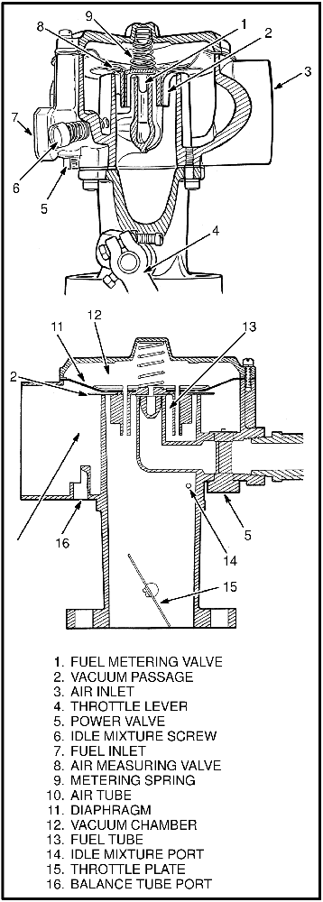
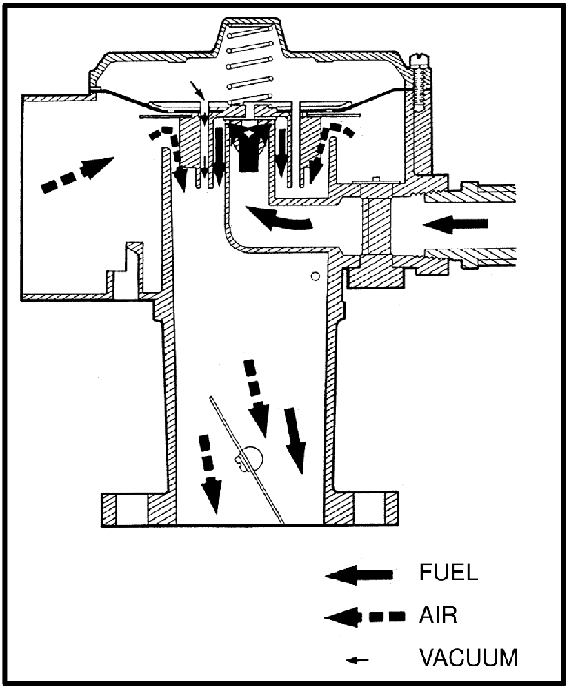
When the engine starts, the air in the air tube and in the vacuum chamber flows to the engine. Air pressure on the outside of the air tube pushes the diaphragm against the metering spring and moves the valves off their seats. Air then flows from the outside of the air tube to the inside, and at the same time the fuel valve is lifted from its seat, so fuel pressure moves LPG vapor from the fuel tube to mix with the air flowing through the air tube.
Because the air measuring valve is a restriction, the pressure inside the tube is always less than the pressure outside it. That difference changes as the amount of air flowing through the tube changes, the diaphragm and valve move according to the air flow, and the fuel that can pass the fuel valve is set by the air entering the air tube.
With the throttle plate near the closed position, the pressure difference decreases, the metering spring pushes the valves toward their seats, and flow through the fuel valve decreases. An air screw for idle permits adjustment of the air and fuel mixture at low engine speed.
With the throttle plate fully open at high engine speed, the valves sit at the top of their travel. An adjustable valve controls the amount of LPG vapor reaching the fuel metering valve. The restriction it creates is small while fuel flow is low; as more fuel flows, the valve becomes an orifice. Adjusting its opening changes the mixture when the engine is worked at high speed with a load.
Piston-type carburetor
In the piston type (the IMPCO CA 50 is the example in this article), the air and fuel valves are part of a piston assembly, and a plate with a check valve holds the metering spring for the piston. The throttle body carries the throttle plate and a valve for the idle air. The body holds the bore for the piston and the seats for the fuel valve and air valve, and the adjusters for the fuel power valve and the idle air mixture are also in the body.
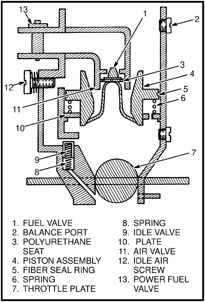
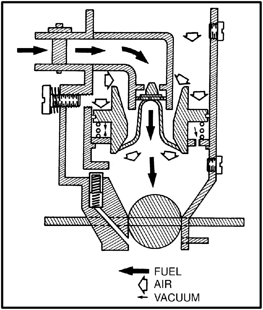
When air enters the carburetor it pushes down on the piston. Because the air valve part of the piston is a restriction to air flow, there is less air pressure under the piston. The check valve in the plate permits air to leave the vacuum chamber and flow past the throttle. Air pressure above the piston compresses the metering spring and moves the air valve and fuel valve off their seats, which lets fuel mix with the air flowing through the air valve. Engine rpm and throttle opening determine how far the piston moves from the seats, and the piston takes a different position whenever engine speed or throttle opening changes.
At idle, vacuum is high in the inlet manifold but only a small amount of air flows past the throttle plate. An idle air screw in the body permits an additional amount of air to mix with the air and fuel mixture during idle, and the piston is pushed down just enough to open the fuel valve. The idle air screw adjusts the amount of air entering the mixture chamber: if more air passes through the idle circuit, less air flows through the air valve, and the piston closes the fuel valve a small amount.
An idle valve permits air from the idle air screw to enter the mixture chamber only during idle. It prevents air flow through the idle circuit while the engine is being started, which causes more fuel to flow for easier starting. When the throttle is opened, the idle valve closes the passage from the idle air screw. A passage is drilled from below the throttle to the idle valve, and when the throttle is closed the vacuum in the inlet manifold pulls the plunger against the spring and opens the valve.
The power valve permits the mixture to be adjusted during full power conditions. It is a variable restriction to fuel flow. During light loads the power valve cannot change the mixture, because its opening is too large to have an effect.
The governor
The governor prevents engine speed from increasing above the rpm specification; a higher speed can cause damage to the hydraulic pumps. It is installed between the carburetor and the inlet manifold.
The mechanical form has a throttle plate connected to a leaf spring and to a vacuum diaphragm. The leaf spring holds the throttle plate open until engine speed has increased to near the specification, and the vacuum diaphragm is used for part throttle operation. The shaft of the throttle plate is not in the center of the plate, so increased air flow closes it. When the air and fuel mixture hits the plate, the plate moves toward the closed position, and it stops closing when the force of the mixture flow equals the spring force. The plate's position changes with the flow of the mixture, which is what keeps the engine at the rpm limit through changing load. The governor is carefully calibrated at the factory and adjustment is not normally needed.
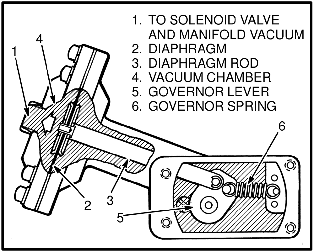
Some governors have vacuum transfer ports for the distributor and the carburetor, with a valve that permits vacuum control of the distributor to adjust spark timing according to load. On some machines a hose connects the diaphragm chamber to the air inlet for the carburetor.
Another form adds an electronic controller. The solenoid valve is installed on the body of the governor, the controller sits in the operator's compartment, vacuum lines connect the governor diaphragm to the solenoid valve and the throttle body, and the controller is wired to the solenoid valve and the ignition distributor. Manifold vacuum still provides the force to actuate the governor, but the controller regulates that force. This governor has two throttle plates connected to a diaphragm: linkage from the diaphragm closes them and a spring opens them.
In operation, the controller receives engine speed signals from the distributor and compares them with an internal reference. When the speed signal exceeds the reference, current flows to the solenoid valve and it closes, allowing manifold vacuum to operate the diaphragm. The diaphragm then works against the governor spring to close the throttle plates and decrease engine speed. The solenoid valve opens and closes as necessary to keep engine speed within the governor limits. When the solenoid valve is not energized it is open, and manifold vacuum does not affect the governor.
What wears out and what fails
The diaphragms, valve pads and gaskets for the vaporizer are supplied together in a repair kit.
- Vaporizer. Pressure reducer diaphragm and vapor valve diaphragm, the valve pads and the gaskets. On inspection, also check the housing for cracks or damage and check the threads.
- Filter unit. The filter element becomes dirty. The valve pad can leak past its seat, and the diaphragm can develop holes or cracks.
- Diaphragm-type carburetor. The diaphragm itself, and the air passages in the metering valve, which must be clean.
- Piston-type carburetor. The throttle seals wear. The piston must move freely in the body, with no scratches on the piston or the bore. If the polyurethane seat is hard or damaged, the piston assembly is replaced. The check valve is also inspected for damage.
- Hoses. Hoses made for hydraulic oil are damaged by LPG. A hose can also leak, be restricted, or be routed too close to the exhaust pipe.
- Cooling side. Low coolant, restricted or undersized water hoses, an air lock in the line to the vaporizer, a loose or broken water pump belt, or a thermostat that is not operating correctly will all show up at the vaporizer.
- Tank. A damaged tank is removed from service, not repaired. If the fuel gauge needle does not move when the tank is moved, the tank is replaced.
- Hydrostatic relief valve. Cannot be repaired. If it is damaged, a new valve is installed.
Working safely on an LPG fuel system
Before disconnecting any part of an LPG fuel system, close the shut-off valve on the fuel tank and run the engine until the fuel lines are empty and the engine stops. If the engine will not run, close the shut-off valve and release the fuel slowly in a non-hazardous area. LPG can cause an explosion even when the tanks are empty.
- Frost on the surface of the tank, the valves or the fittings, together with the odor of LPG fuel, indicates a leak. Inspect the system and repair a leak immediately. Do not attempt to start the engine if there is a leak.
- Do not cause sparks or permit flammable material near the system. When replacing tanks, do not weld or cause sparks on or near them, and do not change tanks while the engine is running.
- LPG is very cold. Wear gloves to protect your hands from cold fittings, do not permit LPG to contact your skin, and use a cloth to protect your hands from cold metal.
- LPG tanks are heavy, and the weight of a tank can exceed the maximum recommended weight for safe lifting by one person. Get assistance and use correct lifting procedures.
- Do not store tanks near heat or an open flame. For complete instructions on the storage of LPG fuels, refer to ANSI/NFPA 58 and 505.
- Tanks must be filled by authorized personnel, and no parts are to be removed from the tank.
- Do not use any LPG tank that is damaged. Damaged tanks must be removed from service.
- The shut-off valve on the tank must be closed when the truck is not being used.
- Cleaning solvents can be flammable and toxic and can cause skin irritation. Follow the solvent manufacturer's recommendations.
Checks and typical figures
The figures below are typical for the kind of system described here. They are included to show the order of magnitude and to make the checks readable, not as a specification for any particular truck.
- Tank pressure, full
- about 1.7 MPa (240 psi) at 27 °C (80 °F)
- Tank pressure relief valve
- set at about 3.4 MPa (480 psi)
- Vaporizer test port, engine at idle
- 10.4 kPa (1.5 psi)
- Test gauge required
- accurate below 35 kPa (5 psi)
- Idle mixture screw, starting point
- 3½ turns counterclockwise from fully closed
- Power mixture valve, starting point
- one notch rich from center
Always work to the service data for your own truck, engine and vaporizer. Idle and governed speeds in particular are set per unit and are not general figures.
Checking the filter unit
- Disconnect the fuel inlet hose at the vaporizer and put the end of the hose in a container of water. There must be no bubbles. If there are bubbles, install a new valve pad in the filter unit.
- If there are no bubbles, remove the primary wire to the distributor, or cause a short circuit in the coil secondary wire. Turn the key switch momentarily to START to cause a vacuum in the inlet manifold. Bubbles must now appear in the water.
- If no bubbles appear, check the vacuum hose for a restriction. If there is vacuum reaching the filter unit, inspect the diaphragm for holes or cracks. Make sure the tank has fuel and that the tank valve is open.
Do not remove the coil secondary wire to cause an open circuit. A spark can cause an explosion.
Checking the vaporizer
Pressure reducer valve. Connect a pressure gauge to the test port of the vaporizer. With the engine at idle the gauge must read the pressure given in the service data — typically 10.4 kPa (1.5 psi). A higher reading means the pressure reducer valve has a problem. Then stop the engine: the gauge must not indicate an increase in pressure. If pressure rises with the engine stopped, the pressure reducer valve has a problem.
Vapor valve. Run the engine until it is warm, then stop it and disconnect the hose from the fuel inlet port at the carburetor. Put the end of the hose just below the surface of water in a container. If bubbles are seen, the vapor valve has a problem or is dirty.
Vapor diaphragm. Remove the inlet hose to the vaporizer and the inlet hose at the carburetor, and put the end of the hose below the surface of the water. Remove the balance line from the carburetor and apply air pressure to the line. If bubbles continue to be seen, the diaphragm has a problem.
Adjusting the carburetor
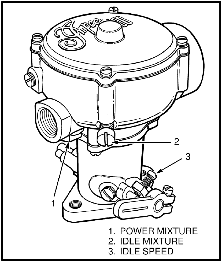
Idle mixture. With the engine not running, turn the idle mixture screw clockwise until it stops; in this position it prevents air from entering the air tube through the idle air port. Turn it 3½ turns counterclockwise, start the engine, and adjust as needed until the idle is smooth. Turning the screw counterclockwise increases the ratio of air to fuel. Then stop the engine and restart it. If it does not start easily, turn the screw clockwise a half turn and restart, and continue until the engine starts easily.
Idle speed. Turn the idle speed screw until the idle speed is within the specification for the unit.
Power mixture. The power mixture valve controls the flow of fuel when the engine is running at near full capacity. Set it one notch rich from center, which is satisfactory for most conditions. If further adjustment is needed, the engine has to be loaded while the setting is made, and engine rpm must not be permitted to rise to the governor limit while adjusting.
- Manual transmission: connect a tachometer, apply the parking brake, start the engine and open the throttle fully, then load the engine by holding a hydraulic function against its relief. If engine speed rises to the governor limit, release the pedal slightly until speed decreases. Turn the power mixture valve until the highest engine speed is reached.
- Powershift transmission: apply the brake and block the wheels so the truck cannot move. Connect a tachometer, start the engine, engage the transmission, fully depress the pedal, and turn the power mixture valve until the highest engine speed is reached.
Adjusting the governor
Before touching the governor, confirm the mechanical, electrical and fuel systems are operating correctly, that the tachometer is accurate and compatible with the ignition system, and that the air filter element is clean and connected.
The main adjusting screw sets the governed speed: clockwise if the engine runs below the governed rev/min, counterclockwise if it runs above. The secondary screw sets how quickly the governor responds. If it acts too quickly, engine speed will hunt at the governed rpm; if it acts too slowly, there will be a large variation between load and no-load speeds. The secondary screw is moved in quarter-turn steps, with a compensating full turn of the main screw each time.
Reinstall the lock hardware after adjusting. If the lock washer and plug are not installed, and the lock washer tab does not engage the slot in the adjusting screw, the governor will not stay in adjustment and there can be a leak in the intake system.
Troubleshooting
| Symptom | Possible cause | Correcting action |
|---|---|---|
| Engine will not start easily, or the vaporizer is freezing | Low coolant level | Check the coolant level at the radiator and the recovery reservoir. Fill to the correct level. |
| Water hoses have a restriction or are too small | Make sure there is adequate water flow to the vaporizer. Install larger hoses. | |
| Air lock in the coolant line to the vaporizer | Remove the air from the coolant line. | |
| Water pump belt is loose or broken | Adjust the tension or install a new drive belt. | |
| Hose from the vaporizer to the carburetor has a leak | Find and repair the leak. Install a new hose. | |
| Thermostat is not operating correctly | Install a new thermostat. | |
| Ignition system does not function correctly, or the starter is damaged | Work through the electrical system troubleshooting for the truck. | |
| Idle mixture screw is not adjusted correctly | Adjust the idle mixture screw. | |
| Fuel valve in the carburetor is damaged | Install a new fuel valve, overhaul the carburetor, or install a new carburetor. | |
| Solenoid valve is disconnected or does not operate correctly | Connect the wire to the solenoid. Install a new solenoid valve. | |
| Air filter is dirty | Check the air restriction indicator. Clean or install a new filter element. | |
| Balance line is disconnected | Connect the balance line. | |
| Accelerating too soon after the engine is started | Allow a longer warm-up time before starting operation. | |
| Engine idle speed is too high | Idle mixture screw is not adjusted correctly | Adjust the idle mixture screw. |
| Idle speed screw is loose | Tighten the screw and adjust the idle speed. | |
| Idle control actuator is not adjusted correctly, or its vacuum hose is disconnected | Connect the vacuum hose. Adjust the idle control actuator. | |
| Engine does not run smoothly | Governor is damaged | Install a new governor. |
| Low pressure diaphragm or valve in the vaporizer is damaged | Repair the vaporizer or install a new one. | |
| Wrong or damaged fuel valve in the carburetor | Repair the carburetor or install a new one. | |
| PCV system has a restriction | Remove the restriction. Install a new PCV valve. | |
| Air leaks in the intake manifold | Repair the leaks. | |
| Balance line has a restriction | Remove the restriction. | |
| Engine does not idle smoothly | Idle mixture screw is not adjusted correctly | Adjust the idle mixture screw. |
| Diaphragm in the carburetor is damaged | Install a new diaphragm or a new carburetor. | |
| Air leak between the carburetor and governor, or between the governor and intake manifold | Fix the air leak. | |
| PCV system has a restriction | Remove the restriction. Install a new PCV valve. | |
| Air leak at the throttle shaft | Repair the carburetor or install a new one. | |
| Hose from the vaporizer to the carburetor is damaged | Install a new hose. | |
| Balance line is disconnected | Connect the balance line. | |
| Pressure reducer diaphragm has a hole | Install a new diaphragm. | |
| Low pressure valve in the vaporizer is damaged | Install a new low pressure valve, or a new vaporizer. | |
| Idle speed is too low | Adjust the idle speed. | |
| Idle speed screw is loose | Tighten the screw and adjust the idle speed. | |
| Water in the fuel | Check the fuel supply and the tank filling procedure. Clean the system. | |
| Fuel tank is installed in the wrong position | Install the fuel tank in the correct position. | |
| Fuel valve on the tank is in the wrong port | Install the fuel valve in the correct port. | |
| Idle control actuator is not adjusted correctly, or its vacuum hose is disconnected | Connect the vacuum hose. Adjust the idle control actuator. | |
| Loss of power | Air filter is dirty | Check the air restriction indicator. Clean or install a new filter element. |
| PCV system has a restriction | Remove the restriction. Install a new PCV valve. | |
| Governor is damaged | Install a new governor. | |
| Power mixture valve is not adjusted correctly | Adjust the power mixture valve. | |
| Hose from the vaporizer to the carburetor has leaks | Repair the leak or install a new hose. | |
| Diaphragm in the carburetor is damaged | Install a new diaphragm. | |
| Wrong type of fuel | Clear the system of the wrong fuel. Fill the tank with the correct fuel. | |
| Hose from the vaporizer to the carburetor has a restriction or is too small | Remove the restriction, or install a new or larger hose. | |
| Vaporizer is damaged | Repair the vaporizer or install a new one. | |
| Engine stops running | Valve on the fuel tank is closed | Open the fuel valve at the tank. |
| Fuel tank is empty | Install a tank that has fuel. | |
| Hose from the fuel tank is too close to the exhaust pipe | Route the hose away from excessive heat. Install a new hose. | |
| Vacuum line to the filter unit is disconnected | Connect the vacuum line. | |
| Filter unit is damaged | Install a new filter unit. | |
| Vaporizer is damaged | Repair the vaporizer or install a new one. | |
| Carburetor is damaged | Install a new carburetor. | |
| Hose to the carburetor is damaged | Install a new hose. | |
| Idle speed is too low | Adjust the idle speed. | |
| Water in the fuel | Check the fuel supply and the tank filling procedure. Clean the system. | |
| Fuel filter is dirty | Service the fuel filter.The source manual says to clean the filter here, and to replace the element in the repair procedure. | |
| Governor is damaged | Repair the governor or install a new one. | |
| Air leak at the intake manifold | Repair the leak. | |
| Solenoid valve is disconnected or does not operate correctly | Connect the wire to the solenoid. Install a new solenoid valve. |
Frequently asked questions
Why does the vaporizer need engine coolant?
A liquid needs heat to change to a gas. When the pressure of the liquid LPG is quickly decreased inside the expansion chamber, heat is taken out of the surfaces of that chamber. Warm coolant flowing through passages in the vaporizer replaces that heat and prevents the vaporizer from becoming too cold to operate.
There is frost on the tank and fittings. Is that normal?
Frost on the surface of the tank, the valves or the fittings, along with the odor of LPG fuel, indicates a leak. Inspect the system and repair the leak immediately, and do not attempt to start the engine until it is repaired. Separately, if a fuel hose has a restriction, it will be coldest around that restriction.
What does the balance line actually do?
It connects the air pressure side of the vapor diaphragm in the vaporizer to an air inlet port at the carburetor. If the air filter becomes restricted, pressure drops in the carburetor and in the vapor chamber. Without the balance line that drop could move the diaphragm and open the vapor valve; with it connected, both sides of the diaphragm see the same decrease, which prevents an increase in the fuel mixture at the carburetor.
Can I use ordinary fuel or hydraulic hose on an LPG system?
No. Hoses made for use with hydraulic oil are damaged by LPG. Use only approved LPG hose in the correct size. When replacing the hose to the quick disconnect fitting, make sure it is the same length as the hose it replaces, because a longer hose lets the tank be installed in a position that is not correct.
The tank valve is open and there is fuel in the tank, but the engine will not run. Where do I start?
The fuel valve in the filter unit is operated by engine vacuum and will not let fuel through unless the engine is being started or is running. Check the vacuum line to the filter unit for a disconnection or restriction, and inspect the valve diaphragm for holes or cracks. The bubble test on the filter unit will tell you whether the valve is opening.
Should the tank shut-off valve be closed when the truck is parked?
Yes. The shut-off valve on the tank must be closed when the truck is not being used, and it must be closed before disconnecting any part of the fuel system.
Can a hydrostatic relief valve be rebuilt?
No. The valve cannot be repaired. If it is damaged, install a new one, then open the shut-off valve slowly and inspect the system for leaks.
Before you order
- Identify which carburetor you have. One design carries the air measuring and fuel metering valves on a diaphragm; the other carries the air and fuel valves on a piston.
- Vaporizer soft parts come as a kit. The diaphragms, valve pads and gaskets are supplied together, and an approved repair kit should be used when assembling the vaporizer.
- The piston is an assembly. If the polyurethane seat is hard or damaged, the piston assembly is replaced rather than reseated.
- Filter element is a separate item from the valve pad, diaphragm and gaskets in the same housing.
- Hose must be LPG-rated and the correct size, and the hose at the quick disconnect must match the original length.
- Tanks and hydrostatic relief valves are not repairable. A damaged tank is removed from service, and a damaged relief valve is replaced.
- Use liquid thread sealant on all threaded fittings at the filter unit and at the vaporizer when reassembling.
We stock vaporizer repair kits, carburetor kits and complete units, filter elements, fuel valves, LPG hose and tank hardware for the common forklift LPG systems. If you are not sure which carburetor or vaporizer is fitted, send us the casting or tag markings and we will identify it before you order.
This article describes how a typical forklift LPG fuel system is built and how it behaves. Pressures, speeds and adjustment values vary between trucks, engines and component versions. As above, work to the service data for your own machine before condemning a part or making an adjustment.